
The World of Power Electronics
Part 2: How Do Switching Power Supplies Work? A Historical Overview of Revolutionary Power Supply Technologies

Electronic devices equipped with ICs and microcomputers require stabilized direct current with little voltage fluctuation. There are two types of stabilized power supplies: linear and switching. Switching power supplies broke through the limitations of conventional linear power supplies, achieving groundbreaking miniaturization, weight reduction, and high efficiency. Switching power supplies embody the key technologies of power solutions.
Why AC adapters based on the linear method are heavy and bulky
An AC adapter, which converts commercial AC to DC, is a good example for learning the basic technology behind power supplies. AC adapters were usually heavy, bulky objects in the past, but they are much lighter and smaller today, exemplified by a mobile phone charger. This is because the switching method has become mainstream since the early 2000s, replacing the conventional linear method.
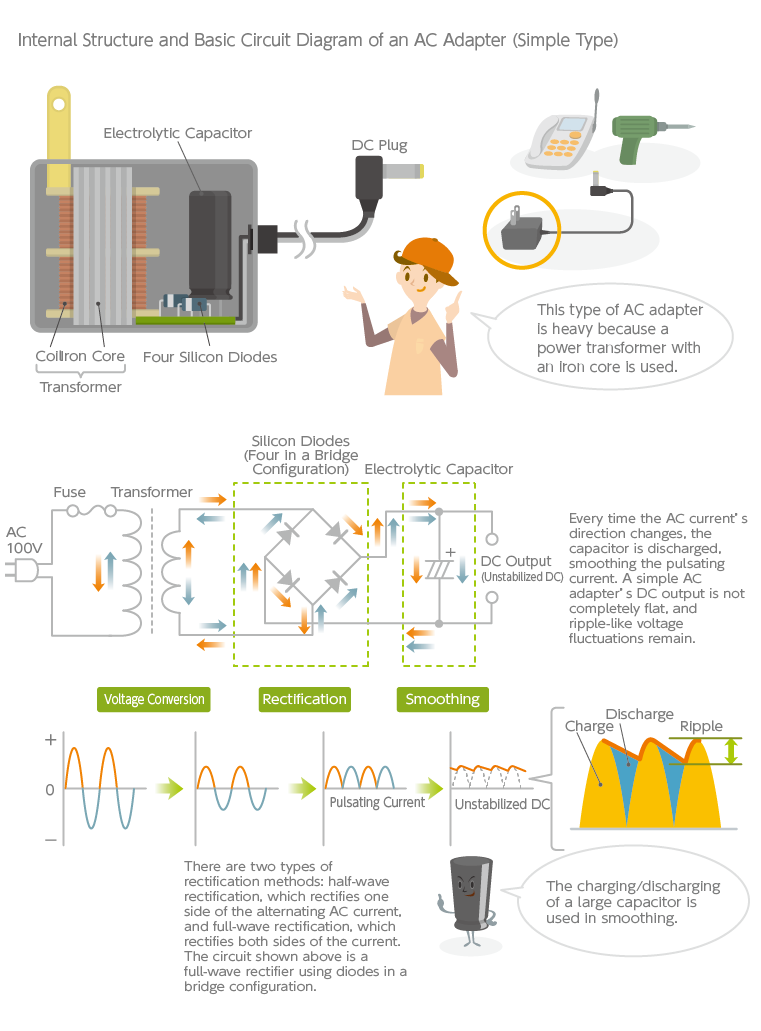
The differences between the linear and switching methods are discussed below, but first, let’s look at a simple, conventional AC adapter—a simple linear power supply without a stabilizing circuit. This type of AC adapter features simple circuitry and low cost, and is used in land-line cordless phones, desktop computer speakers, power tools, etc. Though hard to tell from its external appearance, most of its weight and volume are attributable to the power transformer inside, consisting of a coil wound around a solid iron core. The power transformer converts the 100V AC voltage to a lower AC voltage. Subsequently, the AC current is rectified using diodes—elements that pass current flowing in one direction but block it in the opposite direction.
Even after rectification, the current is still pulsating and far from a clean DC current, so it is further flattened by a smoothing circuit based on a capacitor. A capacitor stores an electrical charge, a fundamental property of a capacitor. The rectifying circuit shown in the figure below is an example that uses diodes in a bridge configuration (a full-wave rectification method). Even when the AC current reverses its direction, the current flowing to the capacitor is always in the same direction, charging the capacitor. In pulsating currents, the current and voltage both fluctuate widely in a cyclical manner, and the capacitor discharges its stored energy accordingly to suppress these fluctuations. High-capacity capacitors are required in smoothing circuits; thus, aluminum electrolytic capacitors are typically used. Additionally, a choke is sometimes placed in series with the capacitor, utilizing the coil’s ability to hinder changes to current, thereby further contributing to smoothing.
Stabilized DC power supplies are critical to digital electronic devices
The function of an AC-DC power supply, such as an AC adapter, is to obtain DC from a commercial AC source. However, the quality of DC varies greatly. In a simple AC adapter, even after the pulsating current is smoothed out, ripples still remain in the waveform. Voltage fluctuations of the commercial AC input can also destabilize the DC output’s voltage. These imperfections may not be a problem for tasks like battery charging, but can cause low-voltage ICs to fail, necessitating a more even and stable DC current. A power supply equipped with a stabilizing circuit (a regulator) for this purpose is called a stabilized power supply.
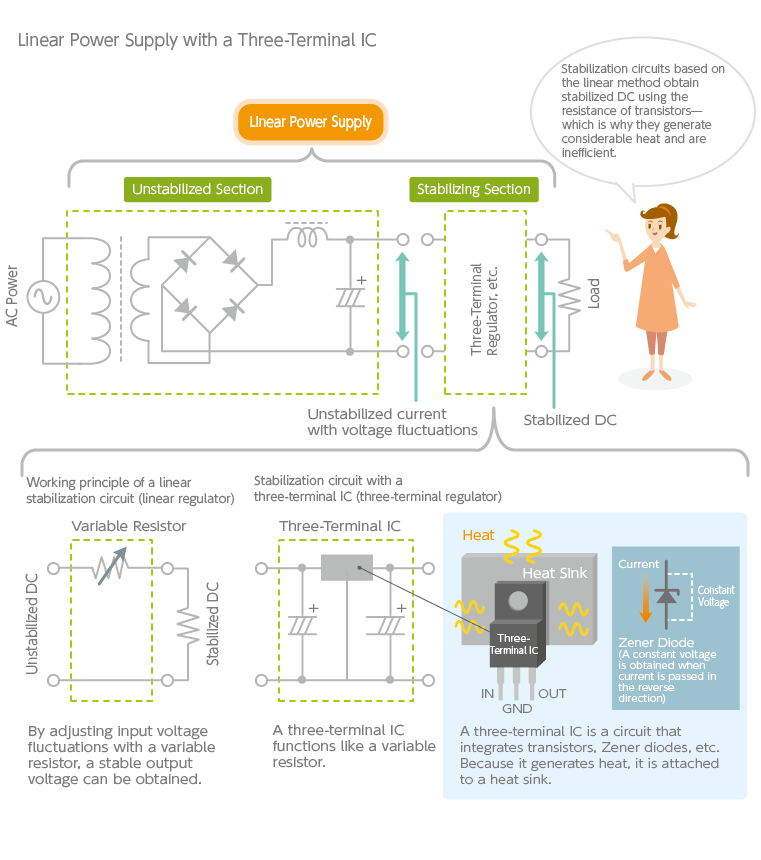
Stabilized power supplies are broadly classified into linear and switching power supplies based on the method used. Linear power supplies have been in use since the days of vacuum tubes. The principle is quite simple: the output voltage is adjusted by incorporating a variable resistor into the circuit. Zener diodes and three-terminal ICs (also known as three-terminal regulators) are examples of components that function as variable resistors.
Zener diodes are also called constant voltage diodes. Regular diodes are used as rectifying elements by allowing current flow in one direction but not in the opposite direction. However, if a voltage is applied in the reverse direction and is continually increased, a threshold will eventually be reached where the diode abruptly begins to pass current. Zener diodes make use of this phenomenon to allow current to flow only above a certain voltage; it can thereby be used to maintain a constant output voltage.
A three-terminal IC is a component that detects the difference between the voltage set by the Zener diode (known as the reference voltage) and the actual output voltage, and stabilizes the voltage by amplifying and correcting it using a transistor. It’s called a “three-terminal IC” because the entire circuit is built on a single chip and features three terminals: IN, OUT, and GND (ground). They have been widely used in electronic devices because of their small size and ease of use. They do generate large amounts of heat, requiring heat sinks for heat dissipation, so they are not suitable for power supplies with large power requirements. However, because of their simple circuitry and low noise, they are frequently used in measuring instruments, medical equipment, and high-end audio equipment.
Switching power supplies have driven downsizing, weight reduction, and high efficiency
We finally get to the explanation of switching power supplies. One of the most common switching power supplies around us is the AC adapter of a mobile phone. While its circuit is far more complex than that of a rudimentary AC adapter mentioned earlier, it is exceptionally compact, thanks to ICs used in the stabilization circuit. The fact that it lacks a large and heavy power transformer explains its small size and weight.
Switching power supplies embody many technologies that have been at the core of power electronics over history. Starting around 1960, semiconductors (diodes, transistors, etc.) began to replace vacuum tubes, but size and efficiency improvements were slow to come. This was intrinsic to linear power supplies because heat sinks were necessary to dissipate the heat from transistors, and the transformers were heavy and bulky.
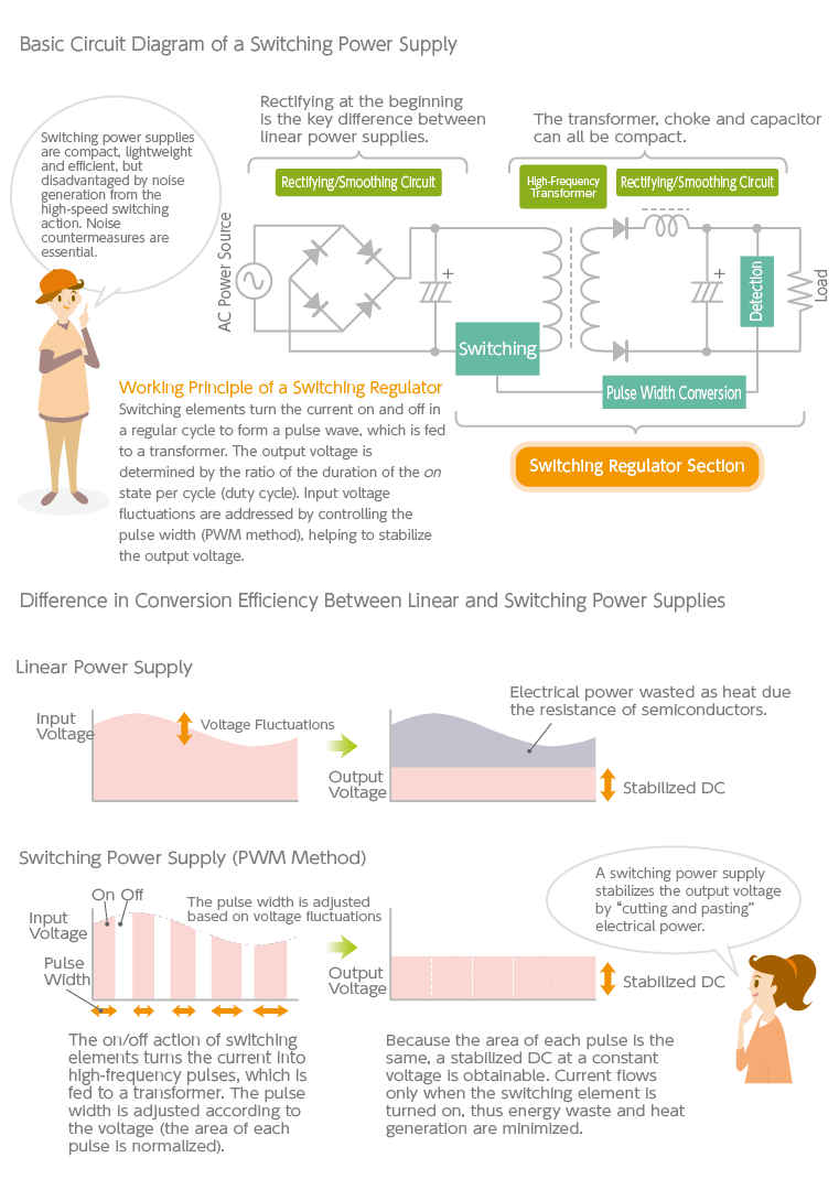
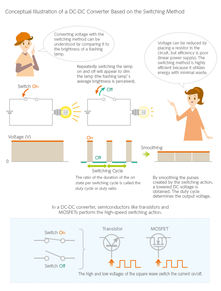
Switching power supplies took a completely different approach to overcome the disadvantages of linear power supplies. (Their development was boosted by NASA’s Apollo program.) The key difference between the two methods is that a linear power supply converts the commercial AC’s voltage using a transformer and rectifies it subsequently; a switching power supply first rectifies the AC to DC and converts the voltage afterward. Once a current is rectified, the voltage can no longer be converted with a transformer. Instead, semiconductors (transistors and MOS FETs) drive a high-speed switching action that converts the rectified current into a pulse wave, which is then fed to a high-frequency transformer that converts the voltage. This complicates the circuit and requires more components, but therein lies the essence of a switching power supply.
Several control methods for switching power supplies exist, but the PWM (pulse width modulation) method is most common. The widths of the pulses (the timing at which the current is switched on and off) are adjusted so that the “area” of each pulse (as represented in a graph) is normalized in an effort to stabilize the voltage. In terms of efficiency, this method is far superior to a linear power supply, which constantly discards part of the power as heat in the course of stabilization. A switching power supply is extremely efficient because it forms the output power as if it were cutting and pasting the waveform, with very little electrical power wasted.
The size of a transformer is inversely proportional to the frequency it is designed to handle. The frequency of commercial AC is a low 50 or 60Hz, so the transformer in a linear power supply is inevitably large and heavy. On the other hand, a switching power supply’s pulse wave frequency is very high—tens to hundreds of kilohertz—where a much smaller and lighter transformer suffices. However, at high frequencies, transformers with iron cores become impractical because the power losses are excessive. This is where a ferrite core becomes indispensable. Just a 1% increase in the efficiency of power supplies, for example, can have a substantial energy-saving effect on society as a whole. This is why expectations are high for TDK’s ferrite technologies in the realm of power electronics. That said, switching power supplies also have their weaknesses: chiefly, the generation of noise due to high-speed switching. Traditionally, power supplies have long represented a battle against heat, and noise is an additional challenge. This is another area where TDK’s technologies come into play.
TDK is a comprehensive electronic components manufacturer leading the world in magnetic technology
Share Share this article
RecommendedPeople who viewed this article also viewed here
The World of Power Electronics
Part 3: The Technologies Behind DC-DC Converter Circuits
The World of Power Electronics
Part 4: The History of Power Electronics Technologies that Spawned the Switching Power Supply

Bridging the Past, Present, and Future of Tech
Smart Homes Revolution: How IoT is Making Homes Smarter and Safer
PickUp Contents