
The World of Power Electronics
Part 3: The Technologies Behind DC-DC Converter Circuits

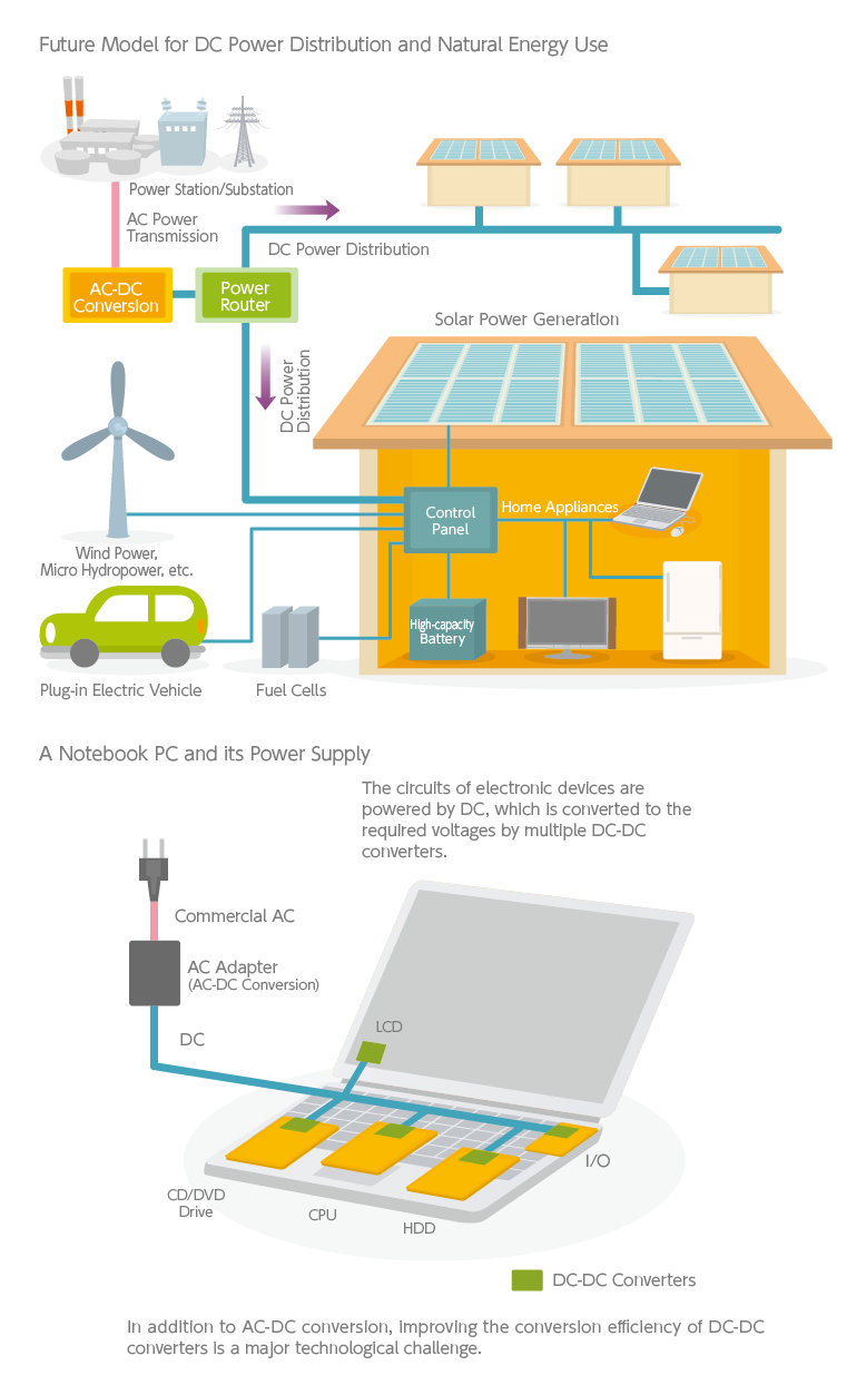
A DC-DC converter is designed to change the voltage of a DC power source. Switching DC-DC converters have excellent conversion efficiencies, contributing to power savings, downsizing and weight reduction of electronic devices. Portable devices like mobile phones are becoming increasingly sophisticated, and are equipped with many small DC-DC converters to drive their circuits.
Power supplies are diversifying along with the progress of electronic devices
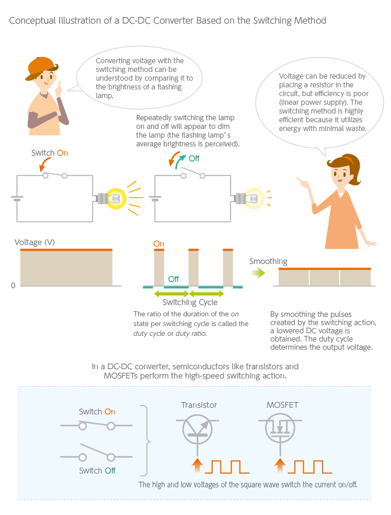
As touched upon in the previous article, DC voltage conversion is achievable using components based on linear methods like a three-terminal IC, but the switching method is predominant among DC-DC converters. The linear method discards a portion of the electrical power as heat to obtain the desired voltage. Meanwhile, the switching method uses semiconductor elements to subdivide the DC input into pulse currents and recombines them to create the voltage needed. The linear method is analogous to cutting a plank out of a log, which inevitably produces a lot of wasteful scrap wood—whereas the switching method is akin to joining wood chips together, enabling more flexible dimensions while consuming less material overall. This explains why the conversion efficiency of the linear method is 70% at best and more typically around 30 to 50%, while the switching method can easily reach 80 to 90% or better.
A packaged switching power supply combines an AC-DC rectifier and a DC-DC converter in a single unit to provide DC output in single or multiple voltages. As electronic devices became more multifunctional and digitalized, multiple DC-DC converters were installed in a device to provide a large set of DC voltages (12V, 5V, 3.3V, 2.5V, 1.8V, 1.3V, 1.0V, 0.8V, etc.) to various circuits individually. Today, many small DC-DC converters are distributed near ICs to improve efficiency and reduce noise. Power supplies have become remarkably diversified along with the progress of electronic devices. In particular, DC-DC converters represent a vast collection of products in the realm of power electronics. Even a rough classification would entail a multitude of types—quickly leading to confusion if not studied in a well-guided manner.
We begin by discussing the basic principles of step-down and step-up DC-DC converters. As shown in the figure below, if a lamp connected to a battery is switched on and off quickly and repeatedly, it appears to dim. This is because we are actually perceiving the average brightness of the flashing lamp, which is equivalent to a voltage drop. It follows that voltage can be controlled by adjusting the timing of the on-off cycle. Albeit a simplified explanation, this is the principle of voltage conversion in DC-DC converters. Semiconductor elements like transistors and MOSFETs are used to switch the current on and off.
Chokes play an essential role in the chopper method
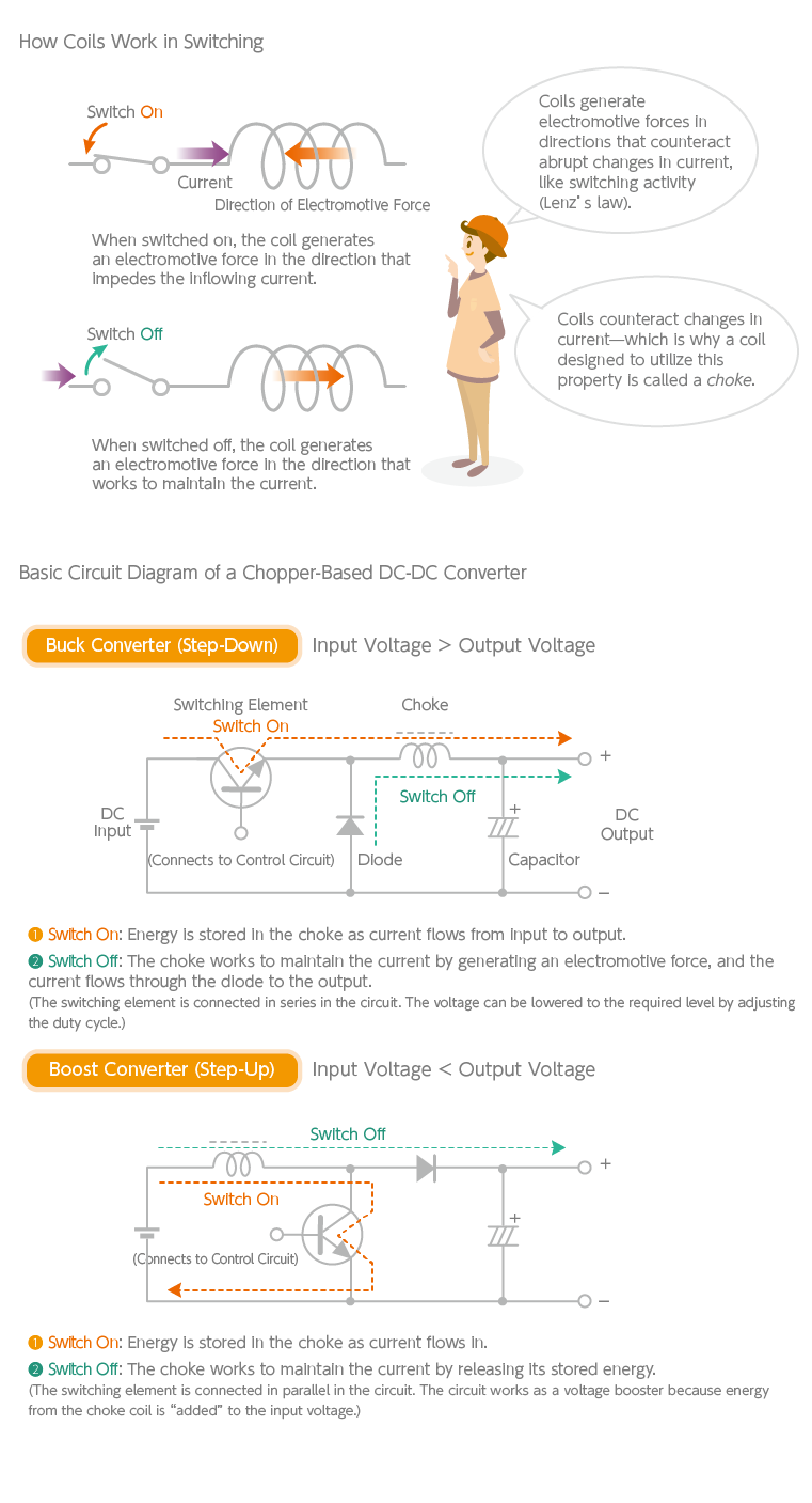
The simplest DC-DC converter is based on the chopper method. The name is derived from the act of “chopping” the current with continuous switching to convert the voltage. Coils play a vital role in the chopper method. Every time the semiconductor element switches on and off, the current flow changes abruptly, but the coil generates an electromotive force (a voltage) that impedes the change by inducing a current (this is Lenz’s law in action). A coil that utilizes this property is called a choke because of the “choking” effect it has on alternating currents. A chopper-based DC-DC converter is a simple circuit that combines a switching element, a choke, a capacitor and a diode in order to step a DC voltage down or up.
Shown below are the circuit diagrams of a basic buck converter (also called a step-down converter) and a basic boost converter (also called a step-up converter)—both of which are chopper-based DC-DC converters. The key to comprehending these circuits is the respective positions of the switching element (a transistor in these diagrams), the choke, and the diode. A choke stores energy when the current is switched on and flows into it—and releases that energy when the current is switched off, inducing a current that acts against the changes in current. Though not explicitly shown in the figure, the base terminal of the transistor is connected to a control circuit, and the square wave generated from it regulates the switching action (triggered by the high and low voltages of the square wave). The longer the current is switched on, the higher the output voltage, and vice-versa—hence, by controlling the on-off durations (called the duty cycle), an arbitrary output voltage can be obtained (this method is known as pulse width control, or PWM). The control circuit is complex, but it doesn’t take up much space as it is in the form of an IC. Capacitors (electrolytic capacitors, specifically) and chokes occupy most of the physical space on the circuit board.
As for chopper-based DC-DC converters, there is another type besides the two mentioned above: one that can both step-down and step-up voltages, called a buck-boost converter. In this type, the orientation of the diodes is reversed from that of a buck converter; it is also known as an inverting type because the polarity of the output is reversed.
Transformer-based isolated DC-DC converters
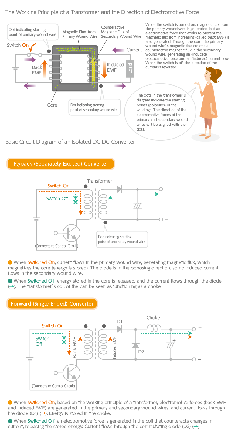
The chopper-based DC-DC converter’s circuit is simple, so they are widely used as small onboard DC-DC converters. DC-DC converters like those based on the chopper method are referred to as non-isolated types, whereas those using transformers (also called switching transformers, etc.) are known as isolated types. A transformer consists of a core (made of iron, ferrite core, etc.) with primary and secondary wires wound around it. When the current flowing the primary wound wire changes, Lenz’s law dictates that a counteractive electromotive force (known as back EMF) is generated. This causes a change in magnetic flux through the core, which generates an (induced) electromotive force in the secondary wound wire, inducing a current flow. The phenomenon is based on the same principle of electromagnetic induction as in a choke. In a choke, it is called self-induction; in a transformer, it is called mutual induction. Just as the chopper method stores energy in the choke, the isolated DC-DC converter cleverly uses energy stored in the transformer to convert voltage. The “isolated” naming refers to the input and output sides being electrically insulated by the transformer. This also helps block conducted noise and prevent electric shocks.
There are various types of isolated DC-DC converters, but the most basic ones are the flyback (separately excited) converter and the forward (single-ended) converter. Their simplified circuit diagrams are shown below (the control circuitry is omitted). The key to understanding these circuits is the transformer. The dots ( ● ) in the diagram indicate the starting points of the wire windings; in other words, they indicate the direction (polarity) of the electromotive forces (back EMF and induced EMF) generated by the primary and secondary wound wires.
In isolated DC-DC converters, polarity is consequential. Lenz’s law tells us that the direction of the electromotive forces of the primary and secondary wound wires will be aligned with the dots ( ● ). Note that the dots are positioned differently with flyback and forward converters.
A variety of isolated DC-DC converters exists, from the basic flyback and forward converters to push-pull and half-bridge types. These types will be covered in more detail in the next article, but broadly speaking, non-isolated DC-DC converters (buck-boost types) are small-capacity; isolated, single-ended flyback (separately excited) converters are also small-capacity; forward converters are small to medium-capacity. The circuitry of medium to large-capacity, multi-element isolated DC-DC converters is far more complex. DC-DC converters constitute a world of technical depth. In the relentless pursuit of higher efficiency, smaller size, lighter weight and lower noise, advanced circuit technologies continue to be poured into this field.
TDK is a comprehensive electronic components manufacturer leading the world in magnetic technology
Share Share this article
RecommendedPeople who viewed this article also viewed here
The World of Power Electronics
Part 4: The History of Power Electronics Technologies that Spawned the Switching Power Supply
The World of Power Electronics
Part 5: Distributed Power Supply Systems and Power Modules

Bridging the Past, Present, and Future of Tech
Smart Homes Revolution: How IoT is Making Homes Smarter and Safer
PickUp Contents