
The World of Power Electronics
Part 4: The History of Power Electronics Technologies that Spawned the Switching Power Supply

Homebuilt radios and amplifiers based on vacuum tubes are seeing a renewed boom. Perhaps it’s related to baby boomers who were electronic hobbyists in their youth now reaching retirement age. Until the middle of the 20th century, vacuum tubes were the stars that drove the progress of electronics. Back then, they were used in power supply circuits that converted commercial AC power to DC. The evolution of power supplies that began in the 20th century continues to this day.
From vacuum tubes to semiconductors, and from linear to switching power supplies
Semiconductors like diodes and transistors have long replaced vacuum tubes, but various technologies inherited from that era are still part of today’s power electronics. Even the diode was named after the original bipolar vacuum tube.
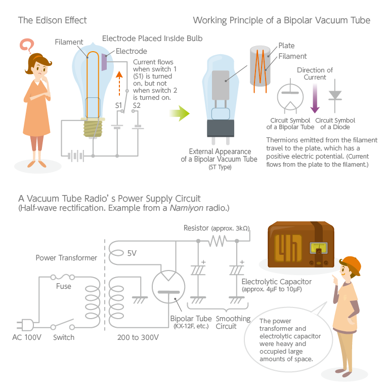
The first vacuum tube was the bipolar thermionic diode, which shares its roots with the incandescent light bulb. In 1884, while experimenting to improve the light bulb he had invented, Thomas Edison discovered that placing an electrode inside the bulb and applying a positive charge to it caused a current to flow between the electrode and the filament across a vacuum. This is known as the Edison effect. Edison was personally indifferent to the phenomenon because it didn’t help improve the light bulb, but John Fleming, a technical consultant to the Edison Electric Light Company at the time, became keenly interested. Noting that current flows only in one direction between the electrode and filament, Fleming theorized that it could be used as a detector to extract signals from radio waves. His efforts culminated in the invention of the bipolar thermionic diode in 1904. The name “diode” derives from di-, meaning “two,” and hodos, meaning “way” in Greek.
Initially used as a detector, the bipolar tube later came to be used in rectifying circuits as well. In the early days of radio broadcasting, receivers were battery-powered. Frequently changing batteries was onerous, so power supply circuits were created to convert commercial AC power to DC. (Crystal radios could receive signals without batteries but weren’t powerful enough to drive speakers.) Shown below is the circuit diagram of the rectifier section of vacuum tube radios colloquially called the “Namisan” and “Namiyon” types, used in Japan around the time of the Second World War. The power transformer and a large electrolytic capacitor used for smoothing comprised most of the weight and volume.
By the 1950s, semiconductors like diodes and transistors were being mass-produced, and power supplies gradually transitioned from the vacuum tube days to the solid-state era. Still, power supplies were slow to become smaller and lighter. As long as the conventional method of first converting AC voltage followed by rectifying the current remained in place, large, heavy power transformers and bulky electrolytic capacitors were unavoidable. Additionally, unlike vacuum tubes, transistors are vulnerable to heat, requiring large heat sinks. A revolutionary breakthrough in circuit technology was needed to downsize and reduce the weight of power supplies. Contemporaneously, space development was emerging, and new forms of power supplies were in demand for space use. It was against this backdrop that NASA developed the switching power supply for the Apollo program.
A switching power supply is like the heart of an electronic device
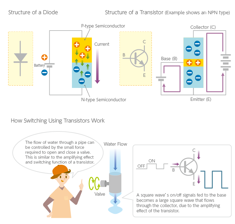
As mentioned frequently in the previous article, switching power supplies control their output using the high-speed switching action of semiconductors, like transistors. Unlike the linear method, where current constantly flows through the semiconductors, the switching method passes current only when the transistors are on, reducing wasteful power consumption and improving efficiency.
The switching method itself was devised in the 1950s. Originally, the AC input was voltage-converted with a transformer before being rectified by diodes, then switched on and off using transistors—thus called a linear switching power supply. It was more efficient than a conventional linear power supply but still required a heavy power transformer, so there was no reduction in weight. Naturally, the next technical challenge was to reduce the size of the transformer. A transformer’s size is dictated by the frequency of the alternating current handled in the primary wound wire. The higher the frequency, the smaller the transformer required. Taking advantage of this property, a method was devised where the AC input is directly rectified using diodes, then switched at high speed and fed into the primary side of a transformer. Special switching transistors able to withstand high voltages had to be developed for this purpose. As a result, the transformer’s size and weight were reduced dramatically, and excellent efficiencies of over 70% were achieved. Circuit and semiconductor technologies responded successfully to the demands for smaller, lighter, and more efficient power supplies.
Today, power supplies that provide the desired DC voltages from commercial AC power sources (referred to as line-operated) are generally called switching power supplies or switching regulators. A switching power supply is like the heart of an electronic device, and it would obviously be convenient if it could be interchanged to match the performance and power requirements of the device. Mass-produced, standardized power supplies emerged from such thinking. In Japan, standardized power supplies first began to appear in the early 1970s. The proliferation of arcade games like Space Invaders, personal computers and vending machines rapidly elevated the importance of standardized power supplies. Their downsizing, weight reduction and efficiency improvements progressed dramatically. Sizes have been reduced to less than one-tenth of what they were back then. They are also available today in a variety of forms like packaged units (covered or exposed) and installable boards to fit different applications.
Fine-tuning rectifier and smoothing circuits
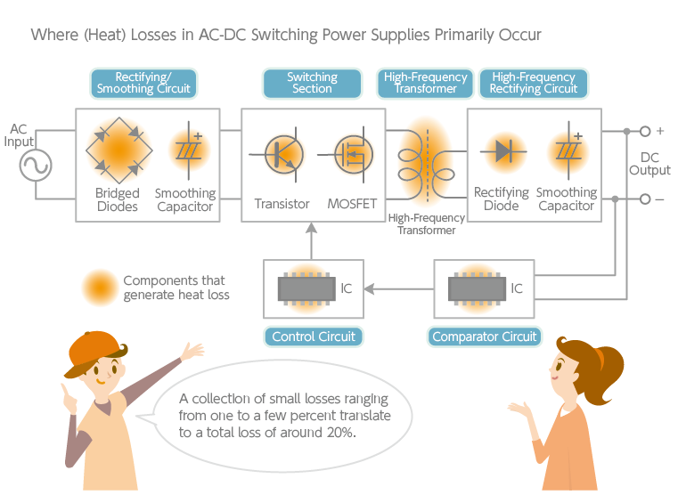
A switching power supply is composed of a rectifying/smoothing circuit; a DC-DC converter that converts the DC voltage; and a stabilizing circuit that monitors the output and provides the necessary feedback to ensure a stable voltage. In addition to these primary circuits, switching power supplies incorporate a variety of other technologies to further improve efficiency and to suppress noise. One example is the inrush current limiter found in a rectifying/smoothing circuit.
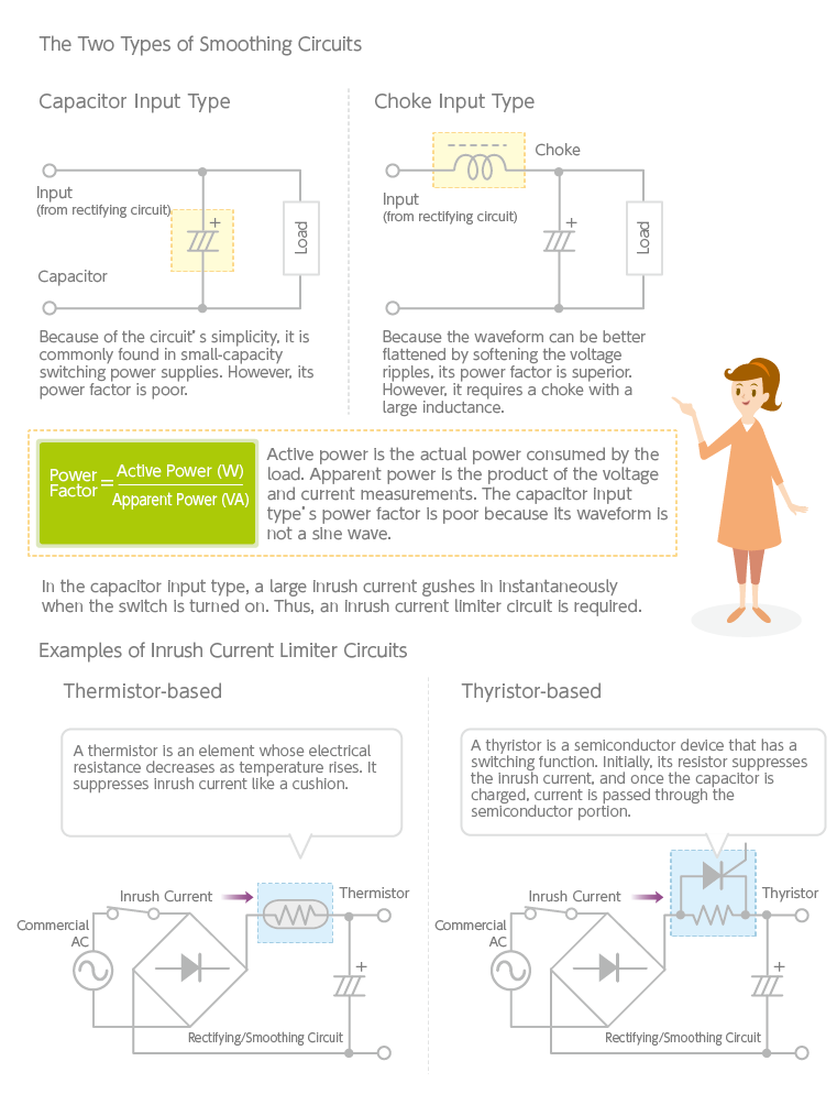
There are two types of rectifying/smoothing circuits in switching power supplies: capacitor input and choke input. A current rectified by a diode is still a pulsating current, and the capacitor input type flattens this by placing a capacitor in parallel directly after the rectifying circuit. While the capacitor input type is simple, it is disadvantaged by a low power factor. The power factor is the ratio of active power to apparent power (the product of actual voltage and current measurements). With a low power factor,
high efficiency is out of the question.
The choke input type offers superior smoothing. It utilizes the braking effect of a coil (self-induction) to improve the power factor by softening voltage ripples. However, the choke inevitably adds volume and weight to the power supply. For this reason, the capacitor input type is prevalent among regular switching power supplies today. (In recent years, power supplies are being equipped with power factor correction circuits to solve this problem—a topic covered in the next article.)
In the capacitor input type, measures against inrush current must be taken. Inrush current is the large, instantaneous current flow that occurs the moment power is turned on. With no choke to moderate the inrush current, an intense current suddenly flows into the capacitor. A simple remedy is to insert a resistor, but this incurs a loss of power and is only applicable to small power supplies. Instead, thermistors and thyristors are more commonly used.
A thermistor is an element whose electrical resistance decreases as temperature rises. As an inrush current raises the temperature, resistance drops, and the inrush current is suppressed with little power loss. In a thyristor-based circuit, a thyristor and a resistor are coupled in parallel. Initially, the thyristor is inactive, and the resistor holds back the inrush current. Just when the capacitor is fully charged, the thyristor turns on, negating the resistor. Even in small circuits that handle inrush current, provisions are made to save power and improve efficiency. Power electronics is a more sophisticated field than one might imagine.
TDK is a comprehensive electronic components manufacturer leading the world in magnetic technology
Share Share this article
RecommendedPeople who viewed this article also viewed here
The World of Power Electronics
Part 5: Distributed Power Supply Systems and Power Modules
The World of Power Electronics
Part 6: The Forefront of Power Supply Technologies for Greater Efficiency

Bridging the Past, Present, and Future of Tech
Smart Homes Revolution: How IoT is Making Homes Smarter and Safer
PickUp Contents