
The World of Power Electronics
Part 6: The Forefront of Power Supply Technologies for Greater Efficiency

The shift from linear to switching power supplies has led to revolutionary improvements in power supply efficiency, size and weight. The evolution of switching power supplies continues today. Power electronics is a fight against losses (mostly in the form of heat). A wide range of technologies and innovations have been applied to components and circuits to achieve higher efficiencies by reducing losses.
Where do losses in switching power supplies occur?
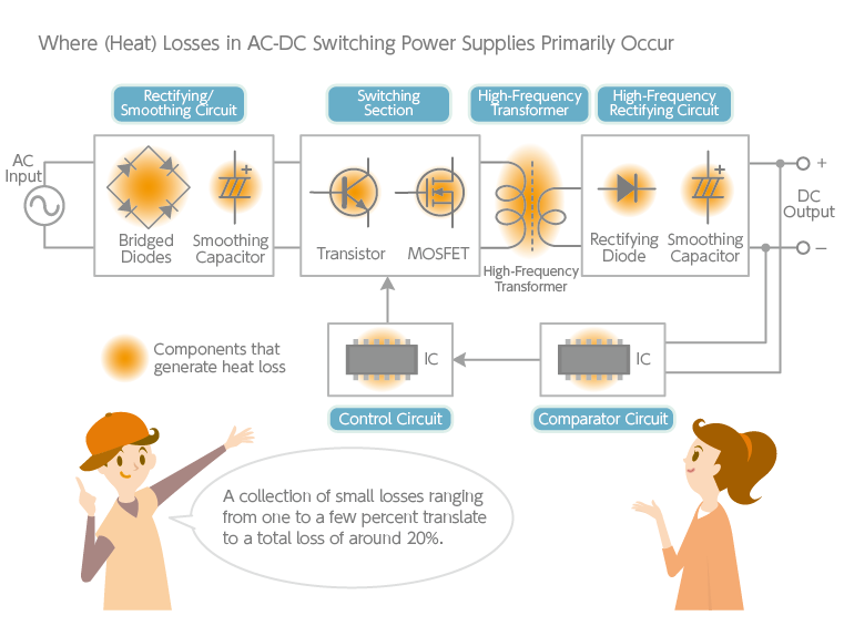
An AC-DC switching power supply used as a power supply for electronic devices consists of (1) an AC-DC front end (rectifying and smoothing circuit) that obtains DC current from 100V commercial AC power, and (2) a DC-DC converter section (including stabilizing circuitry) that converts the obtained DC current to the needed voltage. Despite being much more efficient than linear systems, the efficiency of AC-DC switching power supplies is generally only around 80%. Individual circuit components typically have losses of about one to a few percent, but collectively they translate to an overall efficiency of approximately 80%.
If we take a conventional AC-DC switching power supply as an example, semiconductor elements and transformers have higher losses. In a switching system, commercial AC current is first rectified by a diode such as a bridge rectifier. A loss of approximately 2% occurs here, while another 0.5% or so occurs in the smoothing capacitor after rectification.
The rectified and smoothed DC current is pulsed with a switching element and voltage-converted using a high-frequency transformer. Power MOSFETs, which have lower resistance than power transistors, are now used as switching elements—but again, the high current flow causes a loss of about 2%.
Transformers are another component with significant losses. Whenever a high-frequency pulse current flows through the coil, intense changes in magnetic flux occur inside the core. Ferrite is used as the core material for transformers because, for high-frequency use, iron-based core materials generate too much heat due to eddy current losses (following the same principle as an iron pot heating up in induction cooking). Although ferrite has a relatively low high-frequency loss, about 2% of the energy is still lost in the core—thus, a ferrite material with minimal core loss is preferred. Reducing core loss leads to higher efficiency as well as smaller and lighter transformers. It is important to develop appropriate ferrite materials because the characteristics of ferrite vary with frequency and temperature. Losses also occur in the DC-DC converter section due to semiconductor elements, smoothing capacitors and control ICs. Ferrite technologies matured over the years by TDK are instrumental here.
An innovation in DC-DC converters: synchronous rectification
Improving the efficiency of power supplies is similar to managing a household budget. Reducing losses by using efficient components and circuits as much as possible is much like seeking out low-cost products to minimize expenses. However, “cheap but poor quality” is not a solution. Thus, power supplies are designed with a balance of performance, reliability and cost in mind. In recent years, DC-DC converters are being developed with an efficiency of nearly 95%. One technology that has enabled this revolutionary increase in efficiency is a method known as synchronous rectification. Its principle will be briefly explained here using a buck (step-down) converter as an example.
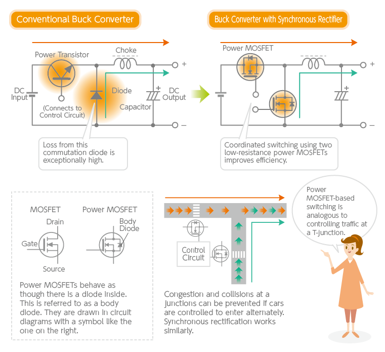
As introduced in Part 3 of this series, a buck converter stores energy in a choke when the switching element is turned on and releases that energy when the element is turned off. In this case, the current flow is maintained in one direction by a diode called a commutation diode (see diagram below). However, losses are exceptionally high because a large current flows through the diode every time it is switched. As a result, low-resistance power MOSFETs are now replacing diodes, as diodes can no longer handle the lower voltages associated with faster circuits. Because power MOSFETs function as switching elements, synchronous rectification buck converters synchronize the switching of two power MOSFETs with a control IC.
Synchronous rectification is akin to cars passing smoothly through a T-junction without traffic lights. If cars merge from two directions, traffic jams and collisions can occur. However, congestion and collisions can be prevented if cars from two directions are controlled to always enter the intersection alternately at the right time and in the right direction. Similarly, synchronous rectification turns two power MOSFETs on and off alternately at the optimal time. This method significantly improves the efficiency of DC-DC converters compared to conventional circuits and even eliminates the need for heat sinks, enabling further size reduction. Also effective in extending battery life, synchronous rectification is increasingly adopted in compact, high-efficiency DC-DC converters for mobile devices.
“Soft-switching” reduces both loss and noise
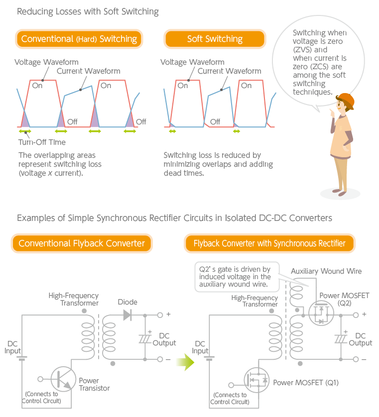
“Soft switching” is a technique applied to synchronous rectification circuits, as conventional switching (also called hard switching) causes a considerable amount of loss. Voltage and current waveforms generated by switching are, in practice, square waves distorted into trapezoidal shapes. Some of the waveforms inevitably overlap when switching on and off—resulting in switching loss. Soft switching attempts to reduce these overlaps. It turns MOSFETs on and off precisely when there is zero voltage and current.
There is also a method of synchronizing two power MOSFETs by creating a “dead time” in-between to prevent them from turning on simultaneously. Furthermore, the voltage and the current phases can be aptly shifted and staggered to reduce loss from overlaps—a technique known as “phase shifting.” Various circuit methods have been devised for soft switching. The essence of this technology is the well-timed control of voltage and current with a minimum number of components.
The buck converter mentioned above is an example of a non-isolated DC-DC converter, but the synchronous rectification method has also been utilized in isolated DC-DC converters with transformers. The diagram below shows an example of a simple synchronous rectification circuit in a flyback converter. It differs from a regular flyback converter in that an auxiliary wound wire is installed on the secondary side of the transformer and is connected to the power MOSFET (Q2). When the power MOSFET (Q1) on the primary side of the transformer is switched off, the energy stored in the transformer core is released, generating a voltage (an induced electromotive force) in the auxiliary wound wire, which drives the gate of the power MOSFET (Q2). The key advantage is that synchronous rectification circuits can be produced at a low cost.
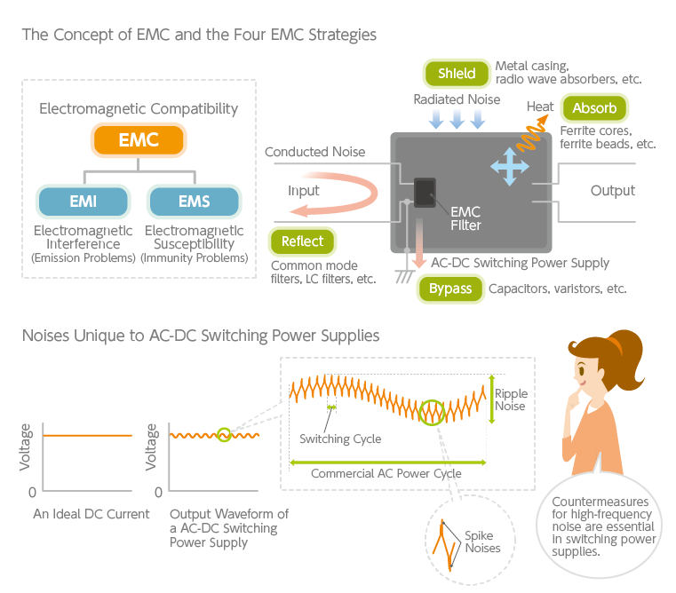
While switching power supplies have achieved remarkable efficiencies, they carry one nuisance — high-frequency noise generated by the switching action. Noise countermeasures in power supplies will be discussed in the next article. Nevertheless, soft switching offers not only the advantage of low switching loss but reduced noise generation as well. For this reason, it has attracted much attention as a leading-edge power supply technology and has seen rapid technological progress in recent years.
TDK is a comprehensive electronic components manufacturer leading the world in magnetic technology
Share Share this article
RecommendedPeople who viewed this article also viewed here
The World of Power Electronics
Part 7: Noise Countermeasures for Switching Power Supplies

The World of Power Electronics
Part 8: Environmentally Friendly, Compact and Lightweight—UPS has Entered the Era of Lithium Batteries

Bridging the Past, Present, and Future of Tech
Smart Homes Revolution: How IoT is Making Homes Smarter and Safer
PickUp Contents