
Intro to EMC Topics
Practical Applications—Part 6: Noise Problems in the 4K/8K Ultra HD Television Era

In 2018, the much-anticipated 4K and 8K Ultra HD television broadcasting began, starting with Japan’s NHK. We are now in an era where we can enjoy ultra-high-definition images that are four to sixteen times denser than current terrestrial digital broadcasting, in vivid colors and with 22.2 channel, 3D sound. Here, we discuss noise countermeasures for TVs in the 4K/8K era, which need to process far more data at much higher speeds than in the past.
The quest for lifelike video
TVs have continued to grow larger in a perpetual quest for more realistic, lifelike video. Human vision needs a horizontal viewing angle of 110 degrees to maximize the sense of realism, which requires watching from a distance of 0.75 times the screen’s height. This necessitates a resolution of 8K (7,680 by 4,320 pixels) to eliminate any perception of graininess and a frame rate of 60 or even 120 frames per second for smooth, realistic motion. The corresponding amount of video data is 144Gbps, more than 100 times the 1.24Gbps bitrate of current high definition television. This is enabled by encoding techniques that compress the amount of video data, and other technologies that minimize the effects of signal latency, use signal paths efficiently, and process signals at high speeds.
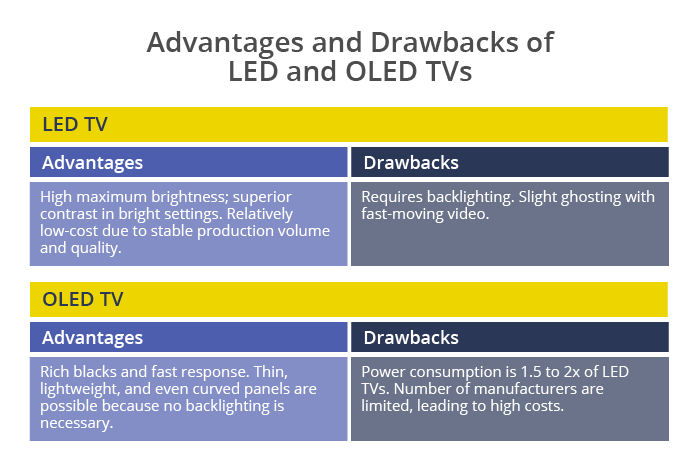
OLED displays, which have many advantages over LCD, are seeing expanded adoption. The imaging principles of OLED and LCD TVs are completely different. In LCDs, liquid crystal molecules are used as electronic shutters to pass or block the backlight to form images. Although they do require a three-color filter for displaying color, high resolutions are relatively easy to achieve. Disadvantages include the need for a backlight since the crystals themselves don’t emit any light, limitations on the viewing angle, and ghosting during high-speed movement such as sports content.
OLED, on the other hand, is based on sandwiching electroluminescent organic compounds between electrodes to emit light. Large-screen displays can be created by arranging individual pixels that illuminate in red, green, and blue, achievable by varying the organic material. Since the pixels emit light on their own, high contrast, wide viewing angles and fast response times are possible. Since no backlight is necessary, OLED displays are thin, light, and can even be curved. These technologies are expected to continue to evolve into displays that better suit the 4K/8K era.
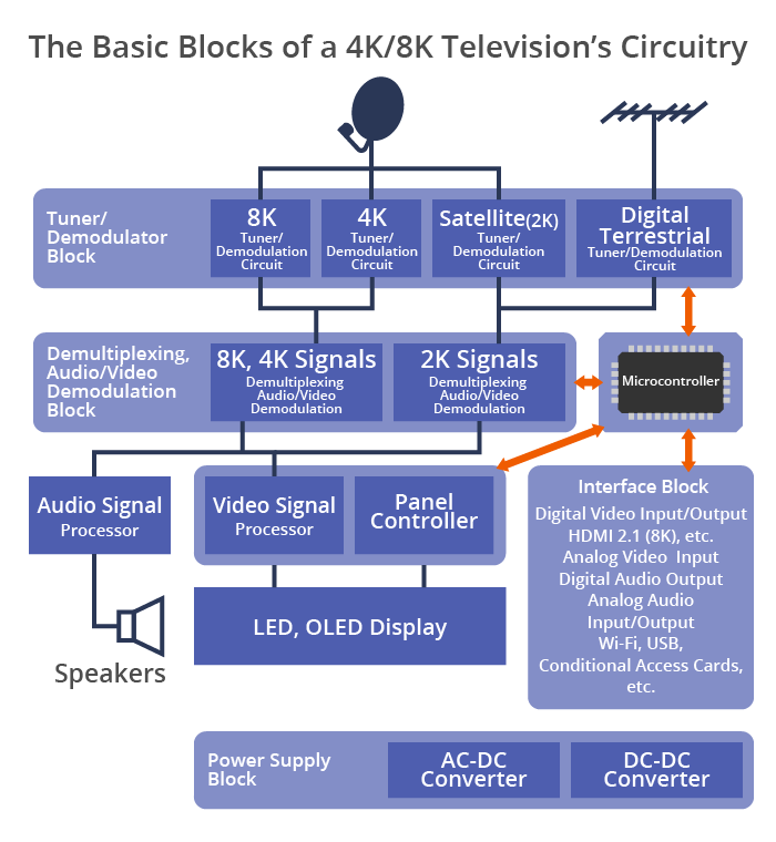
The basic circuit configuration of LCD and OLED TVs is nearly identical, except for the main imaging panel. It consists of a power supply block (AC-DC converter, DC-DC converter, etc.), tuner blocks (digital terrestrial, 2K satellite, 4K/8K satellite), a demodulation/video signal block, a DSP (digital signal processor) block and an interface block, among others. Of these, the video signal processing circuit within the DSP block plays a significant role in determining picture quality.
Digital circuits and noise in televisions
It is commonly believed that digital broadcasting is noiseless. True, noise phenomena distinctive to analog broadcasting, such as overlapping images known as ghosting, and flickering white dots called snow noise, are gone. However, there are some noises unique to digital TVs like block noise, which appears as partial pixelations of the screen, or burst noise, which freezes parts of the video. With analog broadcasts, picture quality degradations tend to be incremental, so you still might be able to make out the image even if there’s, say, some flickering. With digital broadcasting, however, there is no such middle ground—in some cases, there may suddenly be no image or sound at all. For these reasons, digital TVs require extremely high-quality signals, power supplies, and other elements.
In a digital TV, all circuit boards are sources of noise. Of particular concern is switching noise generated by the high-speed switching action of digital ICs. The square wave of a digital signal consists of a high (H) and a low (L) signal level, which are created by turning the switching element inside an IC on and off. When the signal transitions from H to L, or vice-versa, what’s known as a shoot-through current flows momentarily from the power supply to ground. This is the cause of switching noise.
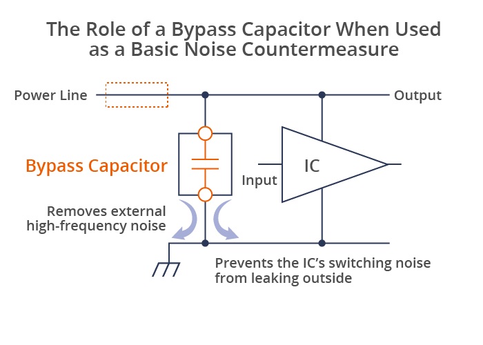
The most basic countermeasure against switching noise in the power line is to insert a capacitor. This is generally referred to as a bypass capacitor. A fundamental property of a capacitor is that it blocks DC current while allowing AC current to pass. If a high-frequency switching current is found to be superimposed on the DC current that powers the IC, inserting a bypass capacitor on the IC’s power supply pin will block the infiltration of external high-frequency noise (by bypassing it to ground) and will also prevent switching noise generated by the IC from leaking.
One ironclad rule of noise suppression is that a bypass capacitor should be placed as close as possible to the power pin of an IC. If the two are placed far apart, the trace patterns between them may behave as an unintended inductor, reflecting the switching noise generated by the IC. If the bypass capacitor alone cannot completely remove the noise, add an inductor or bead. This effectively creates an LC filter that reduces high-frequency noise.
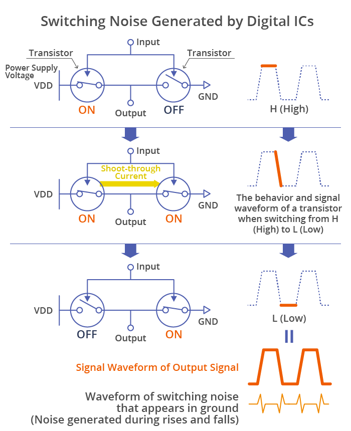
When a signal is switched from H to L (or L to H), there is an instant when the transistors are turned on simultaneously, and a large shoot-through current flows to ground. This is the cause of switching noise.
In some cases, inserting an inductor or a bead serially at the area enclosed in dotted lines in the figure above will improve effectiveness (together with the capacitor, they will function as an LC filter).
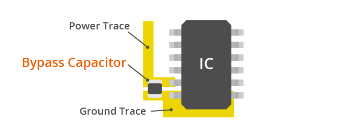
The bypass capacitor should be mounted as close as possible to the IC’s power supply pin. This is because, in high frequencies, even trace patterns can function as an inductor.
Noise suppression components can be counterproductive if selected and used incorrectly
Powerful sound is an important part of a large, flat-screen TV, but image quality is still the definitive factor. Close attention must be paid to video signal processing circuitry that handles digital video signals at high speeds, because they generate harmonic noise (integer-multiple components of the fundamental wave frequency) as the signals are processed. When harmonic noise is superimposed on the square wave of a digital signal, the square wave becomes distorted, causing transmission errors.
Beads and capacitors are used to reduce noise reduction in such signal lines. However, as touched upon earlier, even the external leads of a capacitor can function as inductors in high frequency ranges. The solution to this problem is the three-terminal capacitor, which wraps the signal-carrying electrodes with a ground electrode. Compared to conventional two-terminal capacitors, the three-terminal capacitor has significantly lower ESL (equivalent series inductance), and also reduces high-frequency noise.
When the signal and noise frequencies are close together, a three-terminal filter with steeper attenuation characteristics than a three-terminal capacitor is used. This is an LC filter that combines an inductor, which becomes high impedance in high frequency ranges and blocks noise, and a capacitor, which becomes low impedance and directs noise to ground. They are designed to provide greater attenuation than using inductors and capacitors alone and are available in a wide variety of characteristics. Depending on the internal circuitry, there are L-, T-, π-types, etc., and based on the number of elements, 2nd-order, 3rd-order, 5th-order types, etc.
In general, chip beads, three-terminal capacitors and three-terminal filters—in ascending order—remove noise effectively, but their internal structures become more complex in the same order, typically pushing costs higher in the same direction. EMC measures for electronic equipment with built-in digital circuits require the selection of countermeasure components suitable to each situation—and this is not limited to large, flat-screen TVs. Even three-terminal filters, which have excellent attenuation characteristics, can create ringing, overshoots, undershoots and other disturbances in the digital waveform if impedance becomes mismatched. Noise countermeasures must be implemented carefully, including the use of oscilloscopes and spectrum analyzers.
Just as the symptoms of illness vary from person to person, noise is different for every device. Like medication, noise suppression components can create side effects and be counterproductive if they are chosen and used incorrectly. TDK’s comprehensive EMC solutions provide cost-effective noise suppression using optimal components in minimal numbers.
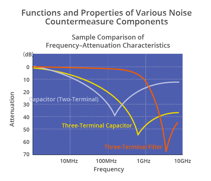
Three-terminal capacitors and filters perform well for noise suppression in high frequency ranges. Three-terminal filters have very steep attenuation characteristics, so they are particularly effective when the signal and noise frequencies are close together.
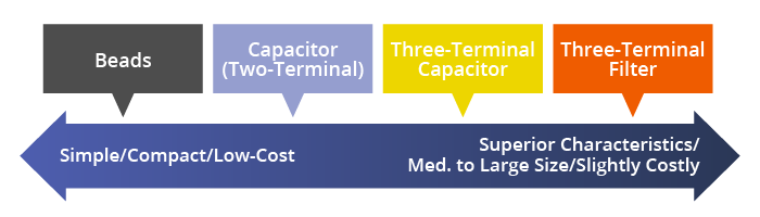
For cost-effective noise suppression, choosing the right components and using them appropriately is key.

A bead behaves as an inductor and suppresses noise in low frequency ranges; in high ranges, it behaves as a resistor and absorbs noise.

A capacitor’s impedance decreases as frequency increases, directing high-frequency noise to ground. It is often connected to the power supply pin of an IC to function as a bypass capacitor.

A three-terminal capacitor wraps the signal-carrying electrodes with a ground electrode, achieving low ESL (equivalent series inductance). It has superior noise removal characteristics in high frequency ranges compared to a two-terminal capacitor.
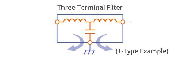
The three-terminal filter is a type of LC filter that features steep attenuation characteristics. It provides greater attenuation than combining an individual inductor and a capacitor. There are variations like the L-, T-, π-types, and are chosen according to the noise condition.

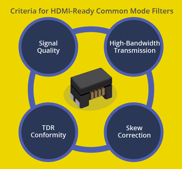
A common mode filter removes only common mode noise while preserving signal quality. Large, flat-screen TVs are usually equipped with HDMI connectors. HDMI is a digital interface that allows the high-speed transmission of voluminous video and audio signals, such as uncompressed high-definition video, over a single cable. TDK’s HDMI-ready common mode filters enable an enjoyable TV viewing experience in the digital age.
TDK is a comprehensive electronic components manufacturer leading the world in magnetic technology
Share Share this article
RecommendedPeople who viewed this article also viewed here
Intro to EMC Topics
Practical Applications—Part 7: EMC Measures for DVD and Blu-ray Recorders
Intro to EMC Topics
Practical Applications—Part 8: EMC Measures for Power Supplies

Bridging the Past, Present, and Future of Tech
Smart Homes Revolution: How IoT is Making Homes Smarter and Safer
PickUp Contents