
Intro to EMC Topics
Components—Part 5: The Common Mode Filter’s Acrobatic Ability to Separate Signals and Noise

Noise propagates in two different ways (called modes): differential mode and common mode. The role of common mode filters is to selectively remove noise propagating in common mode while allowing signals, which flow in differential mode, to pass. These noise suppression components are widely used in high-speed digital interfaces like USB, IEEE 1394, HDMI, and DisplayPort.
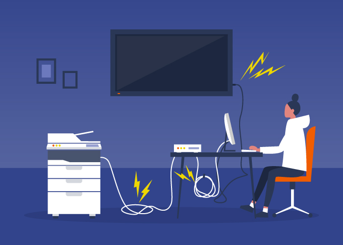
Digital equipment and interface cables are sources of radiated noise. If no countermeasures are taken, the noise radiating from within electronic devices can transform into conducted noise in common mode, adversely affecting devices even at a distance.
The key is to first determine the type of conducted noise
To some extent, all electrical and electronic equipment around us is a source of radiated noise. This can be confirmed in a simple way. For example, if you bring a portable radio close to a working computer or TV, its reception is disturbed, making grinding or beeping sounds. Even a battery-powered digital camera can be a source of radiated noise. In addition to radiated noise, there is conducted noise, which propagates through power and signal lines. Conducted noise can transform into radiated noise via cables acting as antennas and, conversely, radiated noise can turn into conducted noise. Because noise can behave in highly diverse ways and can appear and disappear at will, electronic devices must prevent themselves from becoming noise sources and simultaneously take immunity measures to avoid being affected by external noise. This is the basic concept of EMC.
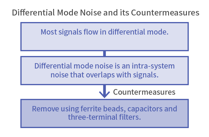
Typically, conducted noise is bypassed to ground by capacitors or absorbed by resistors, ferrite cores, or chip beads and subsequently dispersed as heat. Another important tactic in mitigating conducted noise is leveraging the property of an inductor (coil) to reflect noise and block it. This works because an inductor allows DC current to pass freely, while hindering AC current from flowing due to its high impedance (resistance in AC). However, conducted noise propagates in two distinct modes—differential mode and common mode—requiring countermeasures that accommodate their differences. If the noise’s mode is misidentified, adding noise suppression components to the circuit may even aggravate the noise situation.
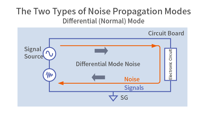
Noise traveling from the source to the electronic circuit through the signal line and back to the power supply side through SG (signal ground) traces. This is called “differential mode” because the directions of current flow on the outbound and return paths are reversed. Most signals flow in differential mode.
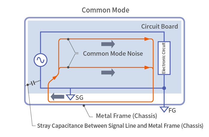
Noise traveling through the signal line and SG (signal ground) in the same direction. Common mode noise is introduced through stray capacitance and magnetic coupling between nearby signal lines.
Common mode noise countermeasures are rising in importance
Differential mode (also called normal mode) is a conduction mode in which the signal line is the outbound path, and signal ground (SG) is the return path. Most signals in an electronic circuit flow in differential mode.
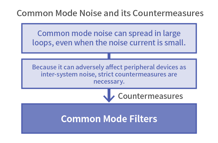
Common mode, on the other hand, is a conduction mode where the outbound and return flows are in the same direction. Common mode noise is caused by issues like an impedance imbalance in the wiring system, and becomes more pronounced at higher frequencies. Worse, since common mode noise can travel through the floor or ground and return in a large loop, it may cause various noise disturbances even in distant electronic devices. This is why, in digital equipment, countermeasures against common mode noise have come to be emphasized in addition to those for differential mode noise.
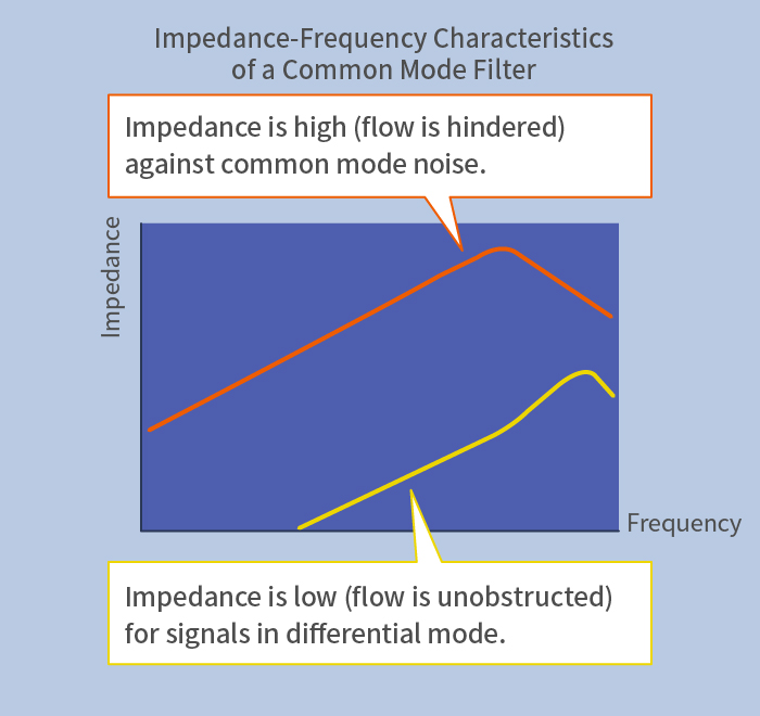
Characteristics required of common mode filters: Pass signals (differential mode) while removing only common mode noise; Do not disturb the signal waveforms of differential transmission signals such as those of USB and IEEE 1394.
For example, cables for high-speed interfaces such as USB, IEEE 1394, HDMI, and DisplayPort use two signal wires (in twisted pairs) with signals flipped 180 degrees in phase. This method is called differential transmission, and it enables extremely high-speed data communication. Differential transmission features low radiated noise and low susceptibility to external noise. In practice, however, an imbalance in the communication characteristics of the two signal lines could engender common mode noise, or the cable could act as an antenna and radiate noise. For these reasons, common mode filters (CMFs) based on the principle of chokes are frequently used in high-speed interfaces such as USB, IEEE 1394, HDMI, and DisplayPort.
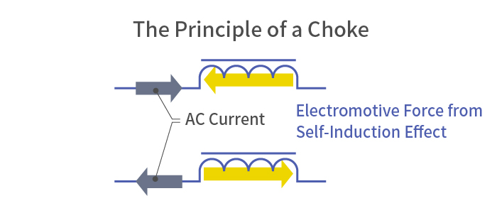
A choke exhibits a braking effect against abrupt changes in current flow, such as AC current, by generating an electromotive force (induced current) in the direction that opposes it (the self-induction effect).
Cleverly separating noise and signals by discerning conduction modes
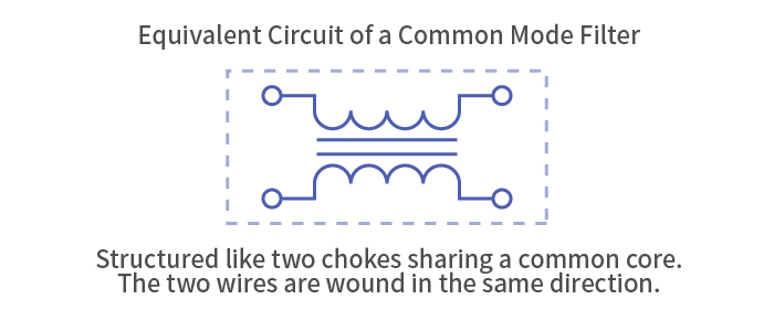
A common mode filter has a structure resembling two choke coils merged into one. A choke is an electronic component with wires wound on a core. When a current flows through the wound wire, a magnetic flux is generated in the core, which acts as a brake against abrupt changes in current flow (the self-induction effect of an inductor). Coils have the property of blocking AC current, which is why they are called chokes.
However, signals—which are in differential mode—and common mode noise are both forms of high-frequency AC current. So why is a common mode filter able to pass differential mode signals while removing only common mode noise?
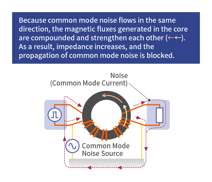
The key is the direction in which the two wires are wound around the core. In a common mode filter, the two wires are wound in the same direction on a single core, which produces a curious effect.
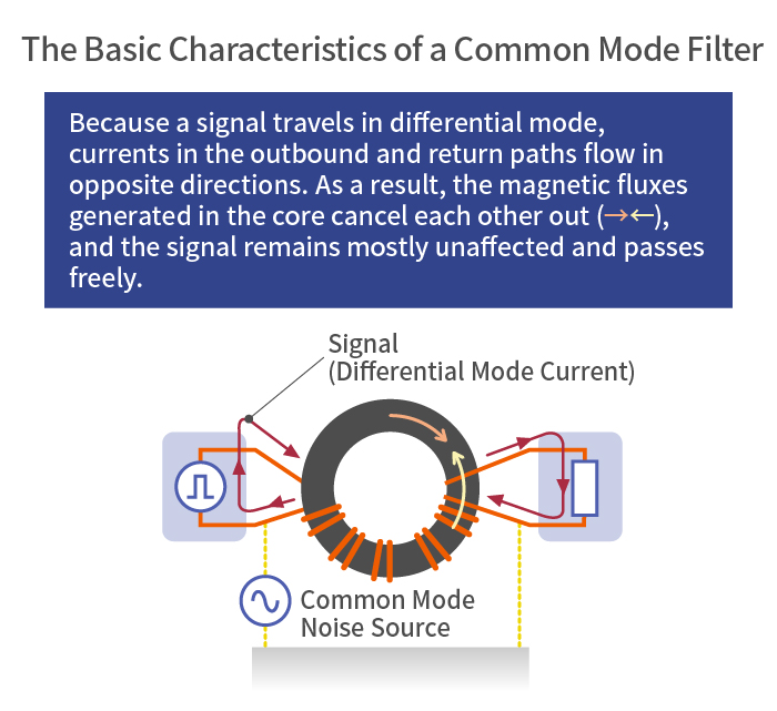
In differential mode, the signal current travels outbound through one wire and returns through the other. The magnetic fluxes in the core are generated in opposite directions, canceling each other out and allowing the signal to pass freely. On the other hand, common mode noise flows in the same direction, so the magnetic fluxes are compounded and strengthen each other. The braking effect becomes stronger, and common mode noise is blocked. This is the basic principle behind the common mode filter. Although it is a tiny component, it is extremely effective. In the age of high-speed, large-capacity networks, common mode filters are becoming critical noise suppression components.
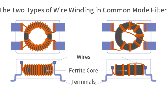
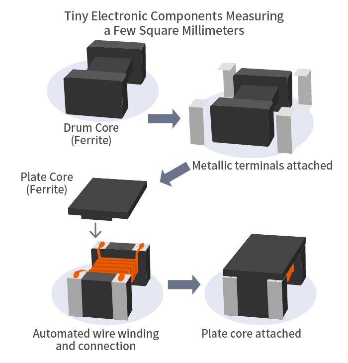
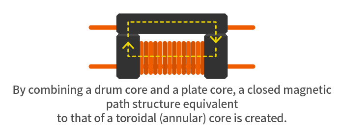
Winding wires on a toroidal (annular) core is difficult. To automate the winding process and achieve miniaturization as well, common mode filters combining ferrite drum cores and plate cores, as shown below, have become mainstream. They are tiny electronic components measuring a few square millimeters only.
TDK is a comprehensive electronic components manufacturer leading the world in magnetic technology
Share Share this article
RecommendedPeople who viewed this article also viewed here
Intro to EMC Topics
Components—Part 6: Suppressing Noise with Snap-on Clamp Filters

Intro to EMC Topics
Components—Part 7: Varistors Protect Circuits by Absorbing Static Electricity

Bridging the Past, Present, and Future of Tech
Smart Homes Revolution: How IoT is Making Homes Smarter and Safer
PickUp Contents