
Intro to EMC Topics
Components—Part 3: The Performance of LC Filters

A capacitor readily passes high-frequency currents; an inductor (coil) doesn’t. When the two are combined, they form a resonant circuit that oscillates at a specific frequency. LC filters (“L” represents inductor; “C” represents capacitor), which selectively remove high-frequency noise, work under the same principle. Today, multilayer, chip-type LC filters play major roles in improving performance, miniaturization, weight reduction and noise reduction of electronic devices.
Invention of the tuned circuit to solve the problem of interference
Adjusting racing cars and machines is referred to as tuning. The word originates from adjusting a musical instrument’s pitch. The tuning fork is a tool that is used to tune guitars and other instruments. As you adjust the tension of a guitar string, the tuning fork produces a “beat” as it approaches a certain frequency. When the beating disappears, the frequencies are matched exactly, and the string is in tune.
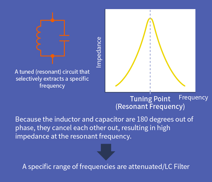
Resonance between two separate tuning forks is also a type of tuning phenomenon. Similarly, when a capacitor and an inductor (coil) are combined, a tuned circuit is created that resonates at a specific frequency. LC filters use the same principle to selectively attenuate frequency ranges that contain noise.
The tuner in a radio or TV is a circuit designed to tune to a specific carrier frequency that contains the signal. The first tuned circuit, which combined a capacitor and an inductor, was invented by the British researcher Oliver Lodge at the end of the 19th century when wireless communication was still in its infancy. Early radio communication devices lacked tuning circuits. But as the number of radio stations grew, so did the problem of interference, and tuning circuits became necessary to isolate communication channels.
One of the easiest ways to understand tuned circuits is the crystal radio. A crystal radio is the simplest form of a radio receiver, composed of a receiving antenna, a tuning circuit, a crystal detector (which behaves like a diode) and a receiver. No power source is necessary, as the energy of radio waves drives the receiver. Until the vacuum tube radio was invented, this was the mainstream type of radio used all over the world.
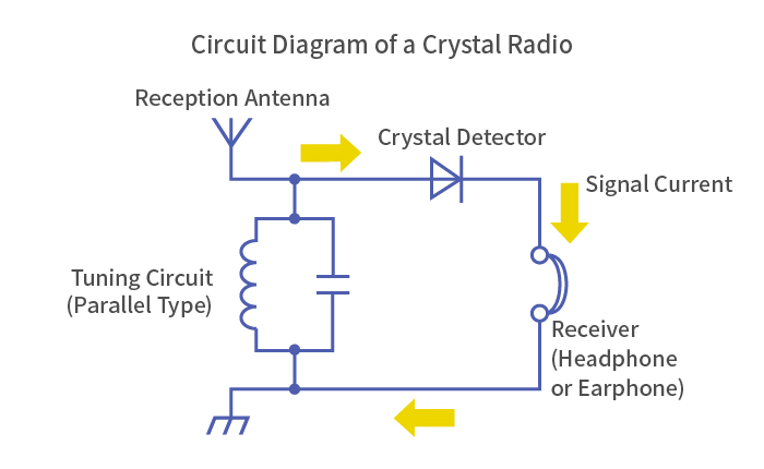
A crystal radio incorporates a tuning circuit, which consists of a capacitor and an inductor connected in parallel (or in series). A variable capacitor, which can continuously change its capacitance, is used to select the broadcast station. There are other types where the capacitance of the capacitor is kept constant, and the inductor’s core is slid back and forth to achieve tuning. This is called a ferrite core tuner.
The LC filter is an application of the resonance phenomenon
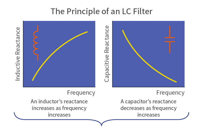
A tuned circuit is also called a resonant circuit. Capacitors do not pass DC current, but with AC current, the higher the frequency, the smaller the reactance (resistance in AC), and the smoother it flows. The phase of the AC current also shifts forward by 90 degrees.
On the other hand, inductors pass DC current well, but with AC current, the higher the frequency, the larger the reactance, and the less smoothly it flows. The phase of the AC current shifts backward by 90 degrees. In a crystal radio, as the current’s frequency is increased, it reaches a point where the current flowing through the inductor and the current flowing through the capacitor, coupled in parallel, become identical. This point is called the resonant frequency. However, because the inductor and the capacitor are 180 degrees out of phase, they cancel each other out, and no current flows in the parallel circuit. Only the current at the tuned frequency flows to the crystal detector, and sound is emitted from the receiver.
A resonant circuit made from an inductor and a capacitor can also be used as a filter. A filter is a circuit that passes signals of a specific frequency range while attenuating, thereby removing, signals in the remaining frequencies.
Filters are broadly classified into the following three types:
Low-pass filter (LPF): Passes low frequencies while attenuating high frequencies
High-pass filter (HPF): Attenuates low frequencies while passing high frequencies
Band-pass filter (BPF): Passes a specific range of frequencies while attenuating frequencies below and above them
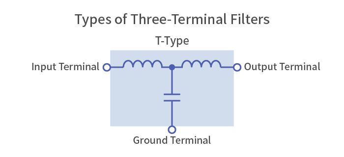
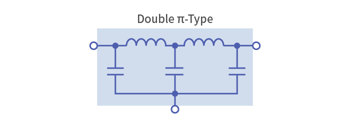
Choosing the right type of three-terminal filter for the noise being generated
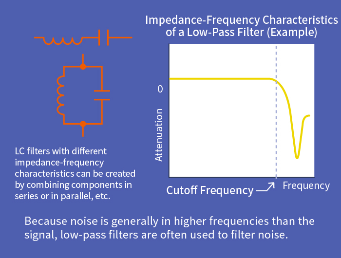
A filter used to eliminate noise that intrudes through a signal line is generally called a signal line noise filter. A capacitor alone can attenuate low frequencies, and an inductor alone can attenuate high frequencies. By combining an inductor and a capacitor, a filter with steep attenuation characteristics above a certain frequency (the cutoff frequency) can be created. This is called an LC filter. The combination of a capacitor and an inductor, which have opposite characteristics, performs exceptionally well for noise reduction.
Conducted noise in electronic devices propagates in two ways: differential mode and common mode. Because signals travel in differential mode, noise in the same differential mode is difficult to remove when it is overlapped with signals. Therefore, noise must be removed using filters at strategic points. Since these noises are generally in higher frequencies than signals, low-pass filters are often used. A three-terminal filter is an LC filter that combines an inductor and a capacitor inside a single component. As the name implies, they have three terminals: an input, an output, and a ground terminal.
There are various types of three-terminal filters with different circuit configurations, and they need to be picked appropriately for the application and the noise being generated. It is especially important to match the impedance on the input/output sides as closely as possible with the impedance at the connection point. If the impedances are mismatched, high-frequency currents may reflect and turn into noise, or the pulse waveform that passes through could become distorted.
A multilayer, chip-type three-terminal filter is a capacitor and an inductor integrated onto a single chip. Because it is produced by continuously layering different materials such as the dielectric, ferrite and electrodes, highly advanced technologies and know-how in material design and firing processes are required. Multilayer, chip-type three-terminal filters—manufactured using TDK’s proprietary techniques for simultaneously firing disparate materials—have enabled the development of high-performance, compact and lightweight smartphones, tablets, digital TVs and other electronic devices. TDK also offers a wide range of products, including wound wire types for power supply lines that help reduce power consumption.


How to read graphs depicting noise suppression characteristics
This is a basic explanation of how to read graphs showing the noise suppression effect of LC filters.
There are two types of graphs, both representing frequency on the horizontal axis. One type depicts impedance on the vertical axis; the other shows insertion loss or attenuation.
Impedance type: This type describes the impedance-frequency characteristics. Generally, the graph is mountain-shaped with a peak in the high frequencies. The higher the frequency, the higher the impedance, and noise suppression is most effective at the peak.
Insertion loss type: A type of graph depicting the difference between output voltages when a noise suppression component is added to the circuit and not, expressed in decibels (dB). It is the opposite of the impedance type, and is usually a valley-shaped graph with a peak in the high frequencies. The higher the frequency, the greater the insertion loss, i.e., the noise suppression effect (attenuation characteristics).
When insertion loss is expressed in decibels, it has the following relationship with the output voltage ratio.
Insertion Loss Output Voltage Ratio
0 decibel 1
20 decibels 1/10
40 decibels 1/100
60 decibels 1/1000
For example, an insertion loss of 20 decibels means that the output voltage will be attenuated by a factor of 10 when the noise suppression component is added. The term “attenuation” is used in much the same way as insertion loss.
TDK is a comprehensive electronic components manufacturer leading the world in magnetic technology
Share Share this article
RecommendedPeople who viewed this article also viewed here

Intro to EMC Topics
Components—Part 4: Noise Suppression Filters for Ensuring High Sound Quality
Intro to EMC Topics
Components—Part 5: The Common Mode Filter’s Acrobatic Ability to Separate Signals and Noise

Bridging the Past, Present, and Future of Tech
Smart Homes Revolution: How IoT is Making Homes Smarter and Safer
PickUp Contents