
Intro to EMC Topics
The Basics—Part 3: The Modes and Behavior of Noise, and the Importance of Differentiating Between Ground and Earth

Noise, while problematic for electronic devices, is a form of electrical energy, just as signals are. Telecommunications has a long history of struggling with noise. The robust communication technologies we enjoy today are the fruits of our relentless efforts to overcome noise problems, and they have come a long way in enriching our lives. As people become more interconnected with sophisticated home appliances, cars, medical care and other services in the future, the stakes couldn’t be higher for noise countermeasure technologies.
Detecting aircraft before there was radar
Radio waves used for communication today are typically microwaves, measuring several centimeters to millimeters in wavelength. At first glance, smartphones may appear to lack any antennas, but there are actually multiple built-in antennas, serving different purposes.
Early in the 20th century, long to medium radio waves were used for wireless communication. Due to the poor sensitivity of receivers at the time, antennas ranging from several hundred meters to as long as a kilometer were strung at heights exceeding a hundred meters above the ground. These long antennas stood out, even from a distance. Because radio communication is a lifeline for the military, radio antennas were the first to be targeted in Europe during the First World War.
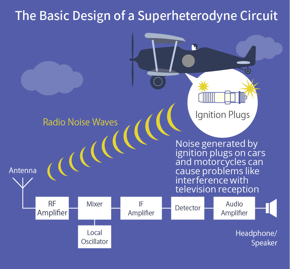
The ignition plugs on airplane engines generate radio noise waves. During World War I, the superheterodyne system was invented to spot approaching fighters by converting these radio waves into detectable frequencies.
Edwin Howard Armstrong, an American electrical engineer who left his mark on the history of 20th-century telecommunications technology, served on the European front as an officer in the communications corps during World War I. To protect the precious communication antennas, he came up with an ingenious idea to foresee the intrusion of enemy aircraft. In a previous article, we noted that Marconi’s early radio telegraph was based on radio noise waves generated by discharge sparks. The ignition plugs on airplane engines do the same. If he could somehow catch these noises, Armstrong figured it might be possible to detect approaching enemy planes. The noise emitted from distant airplanes, however, was weak and in high frequencies. This drove him to invent the technique of converting the high-frequency noise waves to lower frequencies first, then amplifying them to detectable levels. The superheterodyne system was born, and later came to be widely used in radios and televisions.
Minimizing the potential difference between grounds
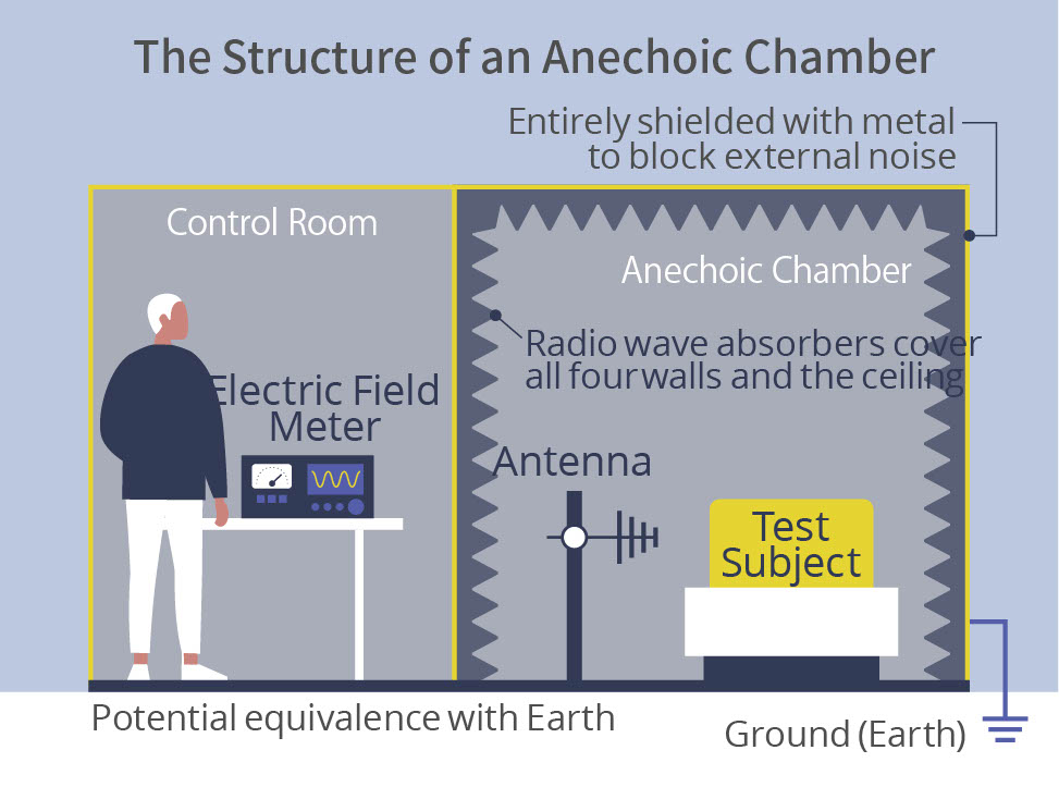
Electronic devices all radiate noise to some extent, while they are also subjected to the interference of noise radiating from external sources. By completely enclosing electronic equipment in metallic casing, they can be protected from external electromagnetic interference. This is because a metal case accepts noise and does not allow it to penetrate inside. This is the simplest example of shielding, one of the four basic methods of noise suppression—the other three being reflection, bypassing and absorption. If the casing is connected to Earth, it is even more effective because the energy of the noise is absorbed by Earth. Accordingly, an anechoic chamber—used for measuring noise emitted from electronic equipment—is shielded entirely with metal and connected to Earth so as to completely block external noise.
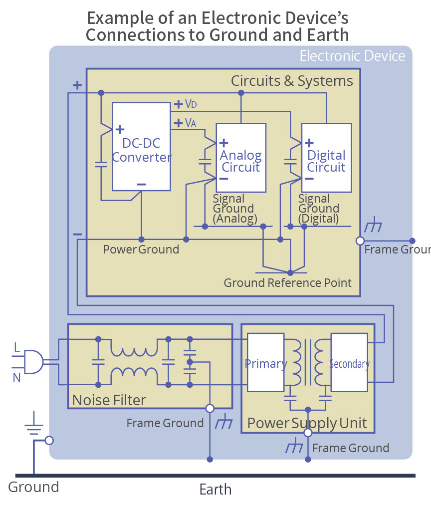
Though often called “Earth,” the proper term for referring to the connection to the metallic casing or chassis of an electronic device, or the circuit board traces used for the signal return path, is “ground.” The metal case and chassis are called frame ground; the board traces are called signal ground.
In electronic devices, it is essential to strictly separate ground and Earth. This is because, even if ground is connected to Earth, the reference potentials of the two could slightly differ and cause noise. This could also occur between frame ground and signal ground, to which analog, digital and power circuits are connected. Therefore, it is desirable to minimize the potential difference between the two grounds—by setting a reference point, for example.
Circuit traces can behave like antennas and radiate noise
Rule #1 in designing circuit board trace patterns: Make ground traces as wide and short as possible, and place them appropriately. Connecting signal ground to frame ground, such as the chassis, is a strategy to maximize the surface area of grounds. If the connection is made with screws, they need to be secured carefully, as loose screws will cause noise to radiate from that area. Serrated lock washers and spring washers help maintain good connections.
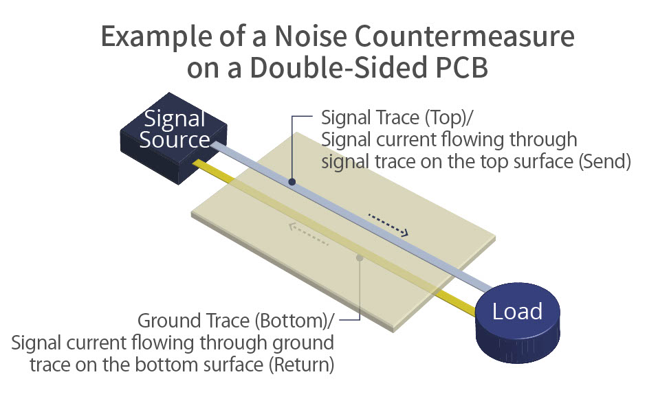
Another rule in designing trace patterns is to avoid creating a large loop with a “hot” signal trace and a signal ground trace, the return path of the signal. This is because loops can behave like antennas and radiate high levels of noise. Most printed circuit boards for electronic devices have signal traces on the top surface, and ground traces on the bottom or in an inner layer. The current returning through ground should be in the shortest distance possible, because resistance should be minimized. This way, the return current will flow directly beneath the “hot” signal trace, diminishing the formation of an antenna loop, a potential source of radiated noise.
TDK is a comprehensive electronic components manufacturer leading the world in magnetic technology
Share Share this article
RecommendedPeople who viewed this article also viewed here

Intro to EMC Topics
Components—Part 1: The Capacitor is the Simplest Noise Filter

Intro to EMC Topics
Components—Part 2: Chip Beads Reflect and Absorb Noise

Bridging the Past, Present, and Future of Tech
Smart Homes Revolution: How IoT is Making Homes Smarter and Safer
PickUp Contents