
Intro to EMC Topics
Components—Part 8: What is an Anechoic Chamber?

There is a growing demand for EMC countermeasures—starting early in the design and development stages of electronic equipment—that do not generate nor are susceptible to electromagnetic noise in the surrounding environment. A high-performance anechoic chamber with excellent traceability and reproducibility is of utmost importance in EMC testing. The anechoic chamber is no longer a simple evaluation tool today but has evolved into a powerful instrument used in product development.
The rising importance of anechoic chambers
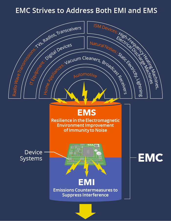
There are many sources of electromagnetic waves around us—electronic equipment, wireless devices and communication systems—which generate a variety of electromagnetic waves. The electromagnetic waves (or noise) generated by such devices may impact nearby devices and vice versa. EMC (Electromagnetic Compatibility) measures address both the problem of emission, the need to suppress the generation of EMI (Electromagnetic Interference), and the problem of immunity or EMS (Electromagnetic Susceptibility), the need to resist intrusive noise. There is an urgent demand for such countermeasures, starting early in the product design and development stages of various devices, to allow a wide variety of electronic, wireless and communication devices to coexist.
The conventional way to measure the electric field strengths of electromagnetic noise generated from electronic devices is at an open-air test site (OATS). However, the disadvantage of outdoor testing is that it is easily affected by weather conditions like wind and rain, and is susceptible to electromagnetic waves coming from the surrounding environment. Additionally, because extremely strong electric fields are irradiated during immunity tests, they cannot be conducted at an OATS due to radio communication regulations. Therefore, the anechoic chamber is becoming increasingly important as a facility that can perform such tests with high reliability and efficiency.
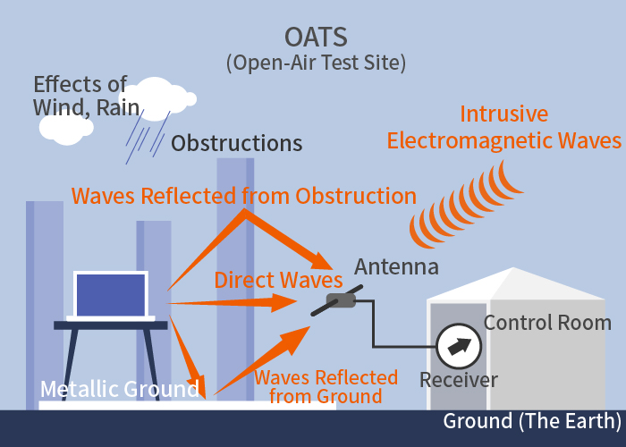
Open-air test sites have too many disadvantages
• Susceptible to intrusive electromagnetic waves
• Susceptible to obstructions
• Affected by weather conditions
• Emission of strong electric fields (immunity test) not possible
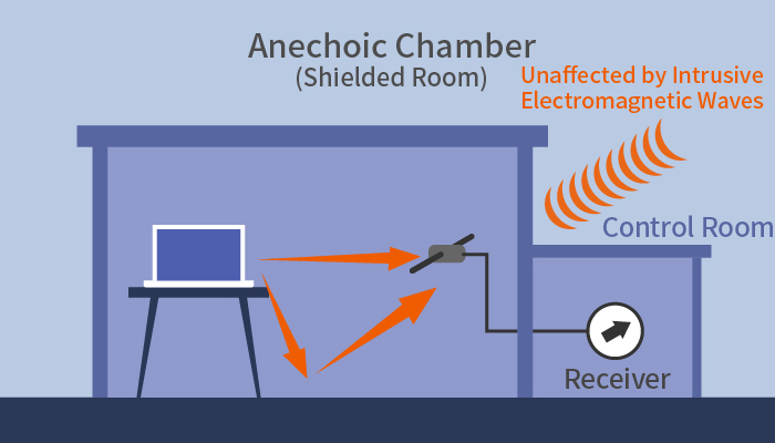
Anechoic chambers have many advantages
• Unaffected by intrusive electromagnetic waves
• Stable test environment
• Electromagnetic interference does not radiate outside
• Tests with strong electric fields (immunity tests) can be performed
• Tests can be kept confidential
Ferrite, the predominant radio wave absorber
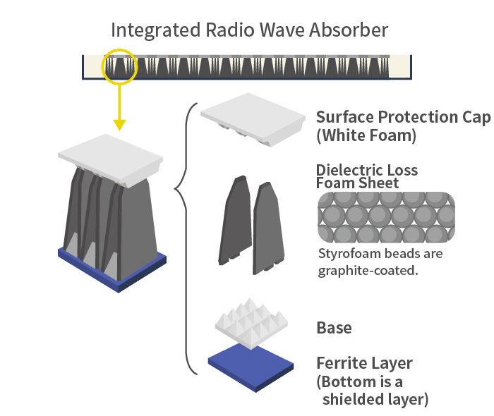
Radio wave absorption materials are classified into three categories: magnetic, dielectric and resistive. Examples of magnetic absorbing materials include sintered ferrite (hereafter referred to as “ferrite”), soft magnetic alloys, and carbonyl iron compounded with resin. However, ferrite is the most common material applied to the walls of anechoic chambers for EMC testing. Ferrite causes magnetic loss (natural resonance, domain wall resonance, etc.) in high-frequency AC magnetic fields. Ferrite-based radio wave absorbers make use of this property. Examples include the absorption of high-frequency radio waves like television waves, which are then converted to heat to reduce ghosting effects seen on TVs caused by waves reflected off high-rise buildings, and to prevent false images on airborne radar. Thanks to production techniques accumulated over the years, ferrite is being developed further as a major radio wave absorber for EMC testing in anechoic chambers.
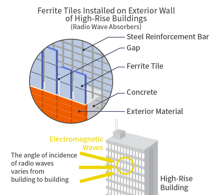
Gaps are placed between ferrite tiles to control their thickness, which optimizes radio wave absorption properties and helps maintain the integrity and safety as a wall material. Ferrite tiles are designed for optimal radio wave absorption according to the specific angle of incidence of radio waves.
Advanced anechoic chambers with new, hollow-tipped pyramidal radio wave absorbers
An anechoic chamber is a shielded space designed and constructed to resist intrusive electromagnetic waves and suppress the emission of electromagnetic waves to the outside world. Anechoic chambers originated in the early 1950s and were initially used for experiments and research on radio equipment and antennas. Since the 1980s, however, when extensive noise regulations were introduced, anechoic chambers have been actively built to evaluate noise emissions of electronic equipment.
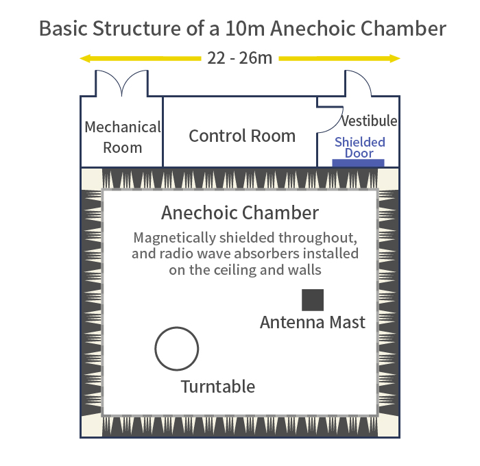
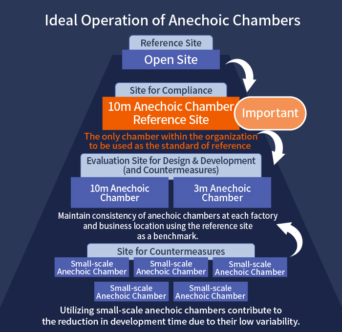
An anechoic chamber is shielded entirely with metal and has radio wave absorbers covering the surrounding walls—five sides (walls plus ceiling) or six sides, including the floor. The size of the anechoic chamber and type of radio wave absorber to be used are determined by the size and purpose of the electronic equipment, wireless devices or communication system being evaluated. 10m and 3m type anechoic chambers are utilized in EMC testing.
In order to ensure the reproducibility of EMC test results, parameters known as “site attenuation” are used as a benchmark. This standard tells whether an anechoic chamber provides an acceptable electromagnetic environment for EMC testing and requires that transmission loss—between the transmitting/receiving antennas and the measuring antennas—falls within specified limits.
Since the EMC Directive went into effect in 1996, noise regulations have been extended to cover large and heavy-duty machinery. With all kinds of household appliances now being equipped with wireless technology, products are more complex than ever before. As a result, the demand for 10m anechoic chambers is growing rapidly.
Radio wave absorbers for 10m anechoic chambers are required to have a wide bandwidth and absorption level of at least 20dB. To achieve these conditions using only a dielectric absorber, the absorber would need to be longer than 5 meters, requiring a huge building. For this reason, professors Kunihiro Suetake, Yoshiyuki Naito and Yasutaka Shimizu of the Tokyo Institute of Technology developed a composite absorber combining ferrite and dielectric materials in the 1960s. Since then, short-length composite absorbers have become mainstream in 10m anechoic chambers.
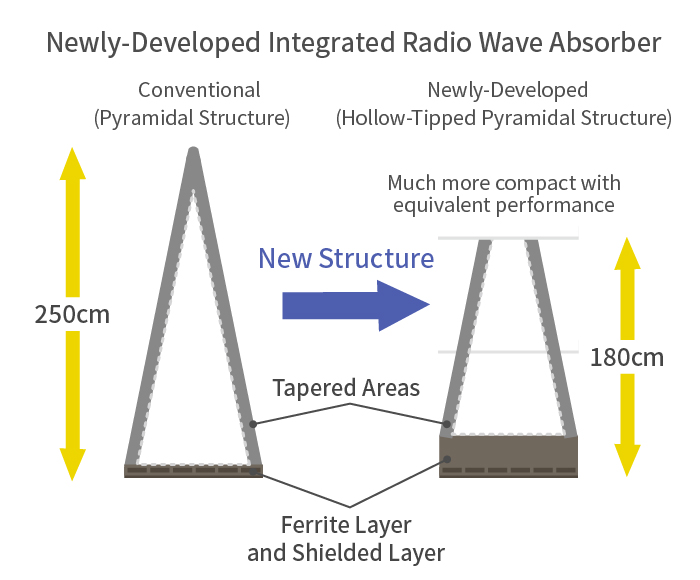
To further improve the performance and shorten the length of composite radio wave absorbers, TDK has developed new, hollow-tipped, pyramid-shaped wave absorbers by combining the best of its accumulated engineering technology. By cutting off the tip of the conventional pyramidal structure, the length of the absorber has been reduced by nearly 30%, resulting in an unprecedented reduction in size and construction time, not only for 10m chambers but all types of anechoic chambers.
Comprehensive EMC solutions with anechoic chambers at the core
Since creating the world’s first ferrite-tiled anechoic chamber in 1969, TDK’s radio wave engineering technology has constantly responded to increasingly sophisticated needs. TDK has delivered more than 1,200 anechoic chambers worldwide, and its design, development, construction and maintenance technologies are highly regarded.
In the future, the frequency of radio waves will eventually expand from microwaves to millimeter and submillimeter waves. One of TDK’s strengths is its extensive lineup of radio wave absorbers for a wide variety of applications. Our anechoic chambers—which use radio wave absorbers with excellent absorption properties in the microwave, millimeter and submillimeter-wave ranges—are making a significant contribution to the research and testing of next-generation smartphones, Wi-Fi, UWB communications, RFID systems and various ITS sensing applications. TDK will continue its contribution to the coming 5G and IoT era by providing comprehensive EMC solutions with anechoic chambers at the core.
TDK is a comprehensive electronic components manufacturer leading the world in magnetic technology
Share Share this article
RecommendedPeople who viewed this article also viewed here
Intro to EMC Topics
Introduction to Noise (EMC) | Practical Applications—Part 1: Noise Countermeasure Technologies for the IoT/5G Era
Intro to EMC Topics
Practical Applications—Part 2: Electrified Cars are Packed with Noise Problems

Bridging the Past, Present, and Future of Tech
Smart Homes Revolution: How IoT is Making Homes Smarter and Safer
PickUp Contents